Grove Published 3-22-2021, Control # 702-02 5-27
GRT8120 OPERATOR MANUAL SET-UP AND INSTALLATION
Accessing the Boom Extension Deployment/Stowage
Function Screen in the ODM
Use the following procedure to access the boom extension
deployment/stowage function screen in the ODM. For more
information about the ODM navigation control pad or jog dial,
see Navigating the Operator Display Module and Rated
Capacity Limiter Display Module, page 4-67.
1. Access the Menu Screen.
2. Use the ODM navigation pad or jog dial to highlight the
Boom Extension Deployment/Stowage icon
(1, Figure 5-30).
3. Press the OK button on the ODM navigation pad or
press down on the jog dial to select the Boom Extension
Deployment/Stowage icon.
The Boom Extension Deployment/Stowage function
screen (Figure 5-29).
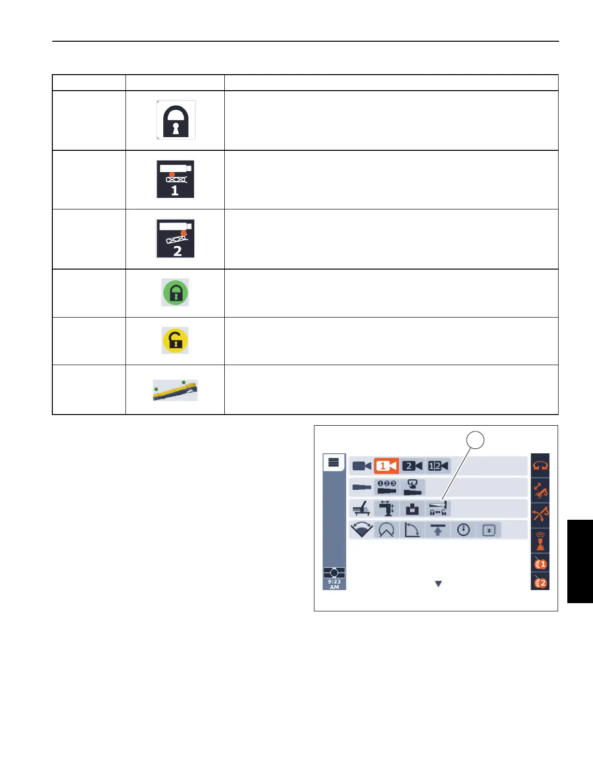
1 and 2 Boom Extension Rear or Front Mounting Pin Locked (Unselected)
1 Rear Boom Extension Mounting Pin (pin #1).
2 Front Boom Extension Mounting Pin (pin #2).
3 and 4 Boom Extension Rear or Front Mounting Pin Status: Locked
3 and 4 Boom Extension Rear or Front Mounting Pin Status: Unlocked.
5
Boom Extension status indicator. This icon changes depending on the location of
the boom extension.
Table 5-2 Boom Extension Group Icons (Continued)
Item(s) Icon Description

 Loading...


