Grove Published 3-22-2021, Control # 702-02 5-67
GRT8120 OPERATOR MANUAL SET-UP AND INSTALLATION
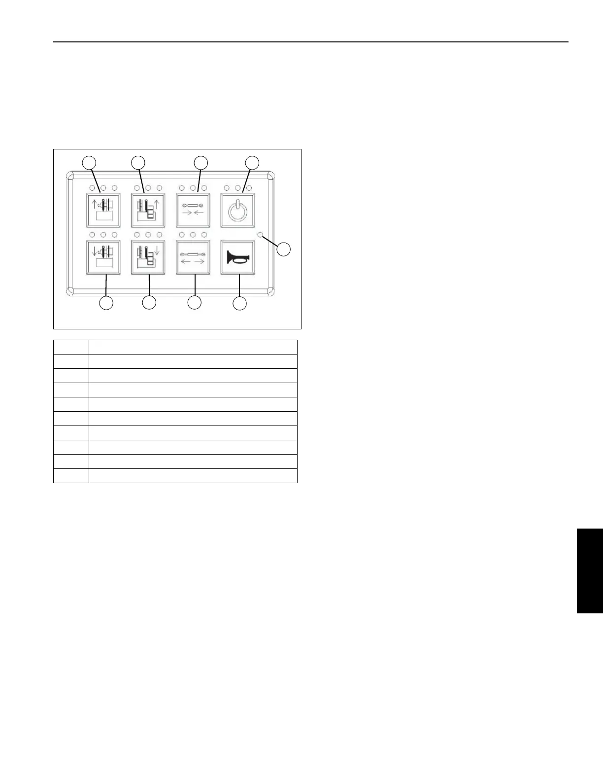
Counterweight Control Panel
Counterweight control panels are located on each side of the
superstructure between the boom pivot and main hoist. Only
one control panel can be used at a time. The crane engine
must be running with parking brake ON and no other
functions enabled for system to be fully operational.
Flashing green LED (1) indicates main power is on. Enable
and Horn buttons are illuminated and active.
Three LED’s above each button indicate:
Green - Function enabled.
Yellow - Error condition.
Red - Function not available or system not enabled.
NOTE: The horn button (3) is always active. Enable does
not have to be pressed before using the horn.
The Enable button (2) must be pressed and released before
selecting a function. The function must be selected within
five seconds after pressing the Enable button or the system
will time out and the Enable button must be pressed again.
If the Enable button is pressed and held for more than
2 seconds, the red LED will illuminate. No other functions are
available until the button is released and pressed again.
Item Description
1 Main Power Indicator
2 Keypad Enable
3Horn
4 Lock Cylinder Retract
5 Lock Cylinder Extend
6 Left Counterweight Cylinder Lower
7 Right Counterweight Cylinder Lower
8 Left Counterweight Cylinder Raise
9 Right Counterweight Cylinder Raise
FIGURE 5-91
8658-2
1
9
8
2
4
7
6
5
3

 Loading...


