Grove Published 3-22-2021, Control # 702-02 3-25
GRT8120 OPERATOR MANUAL OPERATING CONTROLS AND FEATURES
When rear wheels are not centered, the Rear Wheels Not
Centered Alert in the Alerts Area (Figure 4-68) of the
Operating Display Module (ODM) comes on (amber).
If rear wheels are turned to the left, straighten the rear
wheels by pushing and holding the left side of the switch
(turns the wheels right) until the Rear Wheels Not Centered
Alert goes off.
If rear wheels are turned to the right, straighten the rear
wheels by pushing and holding the right side of the switch
(turns the wheels left) until the Rear Wheels Not Centered
Alert goes off.
Swing Brake Release Button
The Swing Brake Release Button (20, Figure 3-9) is located
on the upper front of the left controller.
The swing brake release function is used to align the boom
over the center of the load.
Push and hold Swing Brake Release Button to release the
swing brake. While swing brake is released, slowly reel in
hoist until boom centers itself over the load. Release button
to re-apply the swing brake.
Swing/Telescope or Swing/Auxiliary Hoist
Controller (Dual Axis)
The Swing/Telescope or Swing/Auxiliary Hoist Controller
(21, Figure 3-9) is located on the left armrest.
The controller operates the swing and telescope functions
when crane is not equipped with an auxiliary hoist.
When equipped with an auxiliary hoist, the controller
operates the swing and auxiliary hoist functions. Telescope
function moves to the right controller.
If not equipped with an auxiliary hoist, push controller left or
right for 360 degree continuous rotation of the superstructure
in the desired direction. Push controller forward to extend the
boom. Pull controller rearward to retract the boom.
If equipped with an auxiliary hoist, push controller forward to
lower the hoist rope. Pull controller rearward to raise the
hoist rope.
Move controller in a diagonal direction to operate the two
functions at the same time.
Seat Backrest Adjustment Lever
The Seat Backrest Adjustment Lever (22, Figure 3-9) is
located at the left rear of the seat.
Lift up the lever to allow the seat backrest angle to be pivoted
fore and aft. Once seat backrest is in the desired position,
release the lever to lock the backrest in position.
Seat Adjustment Control Panel
The Seat Adjustment Control Panel (23, Figure 3-9) is
located at the bottom, left side of the seat.
The panel has three electric switches which are used to
adjust the position of the seat and armrest assembly.
The Seat Front Adjustment Switch (1, Figure 3-12) controls
the height of the front of the seat. Pull switch up to raise front
of seat. Push switch down to lower front of seat.
The Seat Rear Adjustment Switch (2, Figure 3-12) controls
the height of the rear of the seat. Pull switch up to raise rear
of seat. Push switch down to lower rear of seat.
The Seat 4-Way Adjustment Switch (3, Figure 3-12) controls
the height of the seat and the seat fore-to-aft position. Pull
switch up to raise the seat and armrests. Push switch down
to lower the seat and armrests. Push switch forward to move
the seat and armrests forward. Push switch rearward to
move the seat and armrests rearward.
To adjust the seat relative to the armrests, use the Seat Slide
Lever (refer to Seat Slide Lever, page 3-23).
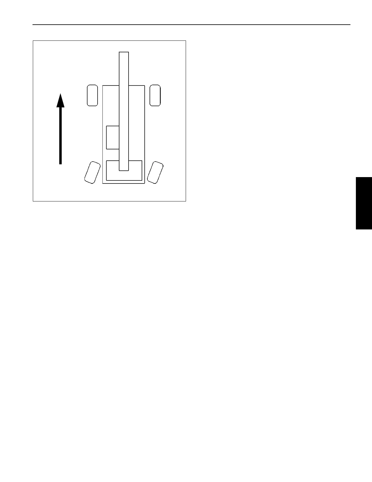
FIGURE 3-11
Direction
of Travel
9898-7

 Loading...


