Grove Published 3-22-2021, Control # 702-02 5-61
GRT8120 OPERATOR MANUAL SET-UP AND INSTALLATION
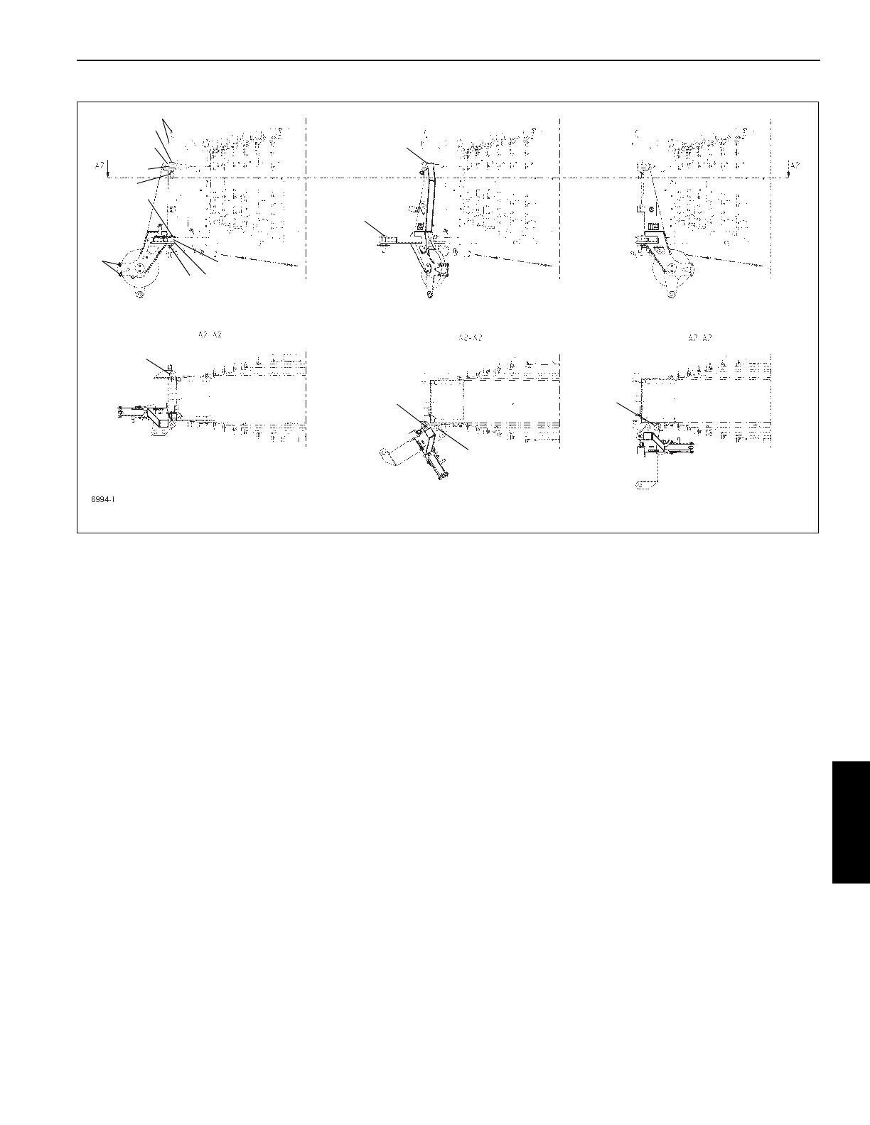
Removing the Auxiliary Single-Sheave Boom Nose
In the working position, the auxiliary single-sheave boom
nose is positioned in front of the main boom head and is
fastened with three pins (3, Figure 5-85).
In the transport position, the auxiliary single-sheave boom
nose is positioned to the side of the main boom head and is
fastened with two pins.
1. Attach an auxiliary crane to the lifting eye of the boom
nose.
2. Remove the retaining clips and remove all the pins out of
the bores and lugs.
3. Lift the auxiliary single-sheave boom nose from the head
of the main boom.
FIGURE 5-85
8994-1
1
2
3
5
1
2
3
3
4
4
Transport Position
Working Position
Intermediate Position
5
6
7
8
9
9
 Loading...


