5-26 Published 3-22-2021, Control # 702-02
SET-UP AND INSTALLATION GRT8120 OPERATOR MANUAL
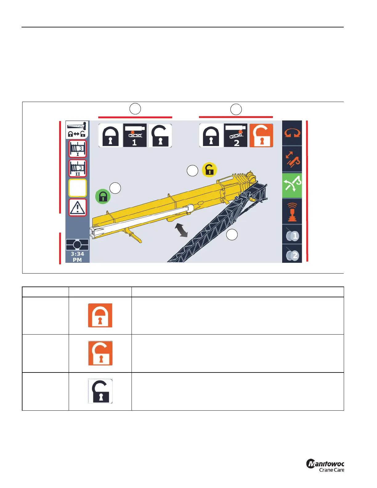
About the Boom Extension Group in the
ODM
Figure 5-29 shows the Boom Extension screen in the ODM.
Table 5-2 describes the icons on the Boom Extension
screen. For more information about the Alerts Area, Active
Screen Indicator Area, and Status Bar, see Using the
Operator Display Module (ODM), page 4-68.
Table 5-2 Boom Extension Group Icons
Item(s) Icon Description
1 and 2 Boom Extension Rear or Front Mounting Pin Locked (Selected).
1 and 2 Boom Extension Rear or Front Mounting Pin Unlocked (Selected)
1 and 2 Boom Extension Rear or Front Mounting Pin Unlocked (Unselected)
5
3
4
2
1
FIGURE 5-29
Alerts Area
(REF)
Status Bar
(REF)
Active
Screen
Indicator
Area (REF)

 Loading...


