MAINTENANCE AND LUBRICATION GRT8120 OPERATOR MANUAL
6-12 Published 3-22-2021, Control # 702-02
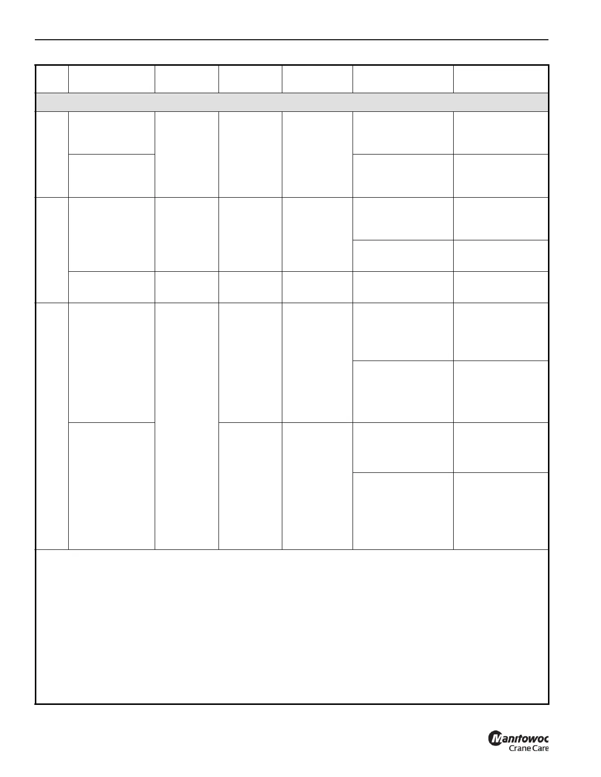
Item
Lube Point
Description
Figure No.
Approved
Lubricant
Approximate
Capacity
Service Interval
Service
Application
Drive Train
1
Engine Air
Cleaner Filter for
QSBT4F-275 HP
Figure 6-1 — —
When engine fault
shows in ODM
See NOTE 3.
REPLACE air
cleaner filter
See NOTE 1.
Engine Air
Cleaner Filter for
QSBT3-275 HP
When indicator
shows red (25
” H
2
O)
See NOTE 2.
REPLACE air
cleaner filter
See NOTE 1.
2
Engine Cooling
System
(Cummins)
Figure 6-1 C
52.7 L(14 gal)
See NOTE 4.
Every 10 hours,
or daily, whichever
interval comes first
CHECK level using
sight gauge (2
A)
See NOTE 5.
LIFETIME
See Service Manual.
DRAIN and FILL
See NOTE 6.
Liquid Cooling
Conditioner (LCC)
Figure 6-1 D As necessary See Service Manual
TEST and ADD
See NOTE 7.
3
Engine
Crankcase
CUMMINS
QSBT4F-275 HP,
with Filter
Figure 6-1
F 20 L (5.3 gal)
Every 10 hours of
service, or daily,
whichever interval
comes first
CHECK oil level
ADD oil to FULL on
DIPSTICK (3
A)
See NOTE 8.
Every 500 hours of
service
DRAIN crankcase
REPLACE filter (3
B)
FILL oil to FULL (3
C)
See NOTE 8.
Engine
Crankcase
CUMMINS
QSBT3-275 HP,
with Filter
F 20 L (5.3 gal)
Every 10 hours
of service, or daily,
whichever interval
comes first
CHECK oil level
ADD oil to FULL
See NOTE 8.
Every 500 hours of
service
See NOTE 9 when
using sulfur fuel that
is >5000 ppm (it is
not recommended)
DRAIN crankcase
REPLACE filter
See NOTE 9.
FILL oil to FULL
See NOTE 8.
NOTE 1: REMOVE decking side cover to access Engine Air Cleaner Filter element.
NOTE 2: CUMMINS QSBT3-275 HP – REPLACE Air Cleaner Primary Element when Indicator shows Red (25
” H
2
O).
NOTE 3: CUMMINS QSBT4F-275 HP – REPLACE Air Cleaner Primary Element when engine fault comes on in the
Crane Vitals Area of the Operator Display Module (ODM).
NOTE 4: Anti-Freeze Coolant (AFC) capacities indicated are for a fully formulated mixture of 50% AFC and 50% water.
NOTE 5: CHECK Coolant level using sight gauge (2
A) visible through radiator grille at rear of crane. FILL Surge Tank to
bottom of filler neck. OPERATE engine through two (2) thermal cycles. CHECK coolant level and FILL as
necessary.
NOTE 6: See your GRT8120 Service Manual for specified coolant fill instructions.
NOTE 7: See your GRT8120 Service Manual for information about Liquid Cooling Conditioner (LCC) levels and testing.
 Loading...


