OPERATING PROCEDURES GRT8120 OPERATOR MANUAL
4-170 Published 3-22-2021, Control # 702-02
The crane movements are reactivated when you have
returned to a normal operating state below the maximum
permissible load capacity – lamps (1, Figure 4-205) and (2)
go out.
Limit Bypass Alert Indicators
In an emergency situation only, the Limit Bypass Switch
located in the cab on the right overhead control panel can be
used to bypass the different limiter systems on the crane.
Refer to the following pages for information regarding the
switch’s operation:
1. Momentary Limit Bypass Switch (Non-CE Certified
Cranes), page 3-10
2. Limit Bypass Set-Up Switch (CE Certified Cranes), page
3-10
A Limit Bypass Switch is also located in the cab behind the
operator’s seat on non-CE certified cranes and on the
outside rear of the cab on CE certified cranes:
3. Maintained Limit Bypass Switch (Non-CE Certified
Cranes), page 3-37
4. Bridging Switch (CE Certified Cranes), page 3-42
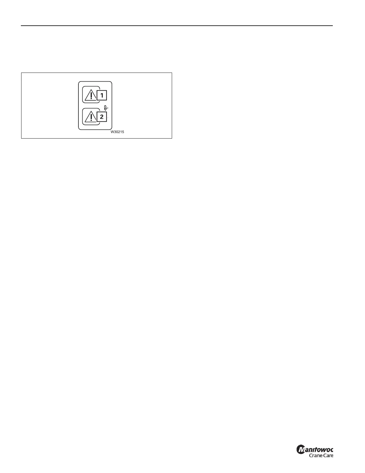
When a Limit Bypass Switch is actuated, the following
indicators on the Rated Capacity Limiter Display Module
(RDM) come on to confirm that the limiters are bypassed (1
and 2, Figure 4-206).
Load Chart and Miscellaneous Alerts
Refer to Figure 4-206 for a list of alerts and their definitions
that can appear at the bottom of the Main Screen of the
RDM.

 Loading...


