5-34 Published 3-22-2021, Control # 702-02
SET-UP AND INSTALLATION GRT8120 OPERATOR MANUAL
Removing the Folding Boom Extension
Use the following procedure to remove the boom extension
from the boom nose.
NOTE: This procedure assumes the boom extension is
erected on the boom nose and the fly section is
stowed on the boom extension base section. If the
fly section is erected, stow the fly section. For more
information, see Stowing the Fly Section, page
5-41.
This procedure would also be used to remove only
the boom extension base section. In this case the
fly section must be left stowed on the boom base
section.
1. Make sure the crane is set up on fully extended
outriggers. For more information, see Using the
Outriggers, page 4-19.
NOTE: An auxiliary crane with sling is required to remove
the boom extension from the main boom.
2. Fully retract and lower the boom to horizontal.
3. If necessary, remove the anemometer and boom
position light. For more information, see Anemometer/
Boom Position Light (Optional), page 5-63.
4. Remove the anti-two block switch from the end of the
boom extension. For more information, see Anti-Two
Block Switch on the Boom Extension, page 5-58. Install
the anti-two block switch on the auxiliary boom nose. For
more information, see Anti-Two Block (A2B) Switch,
page 5-10.
5. Unreeve the hoist rope from the boom extension
sheaves. For more information, see Reeving the Hoist
Rope, page 5-55.
6. Using a sling attached to an auxiliary crane, attach the
auxiliary crane to the boom extension attaching points.
For more information about attaching points for the sling,
see Lifting Points, page 5-25.
7. Attach a tag line to the end of the boom extension base
section with the nose sheave.
8. Lower the mast sheave assembly. For more information,
see Folding Mast Sheave, page 5-59.
9. Disconnect and stow the boom extension electrical
connections from the main boom. For more information,
see Boom Extension Electrical Connections, page 5-51
10. If removing a hydraulic boom extension, disconnect and
stow hydraulic connections. For more information, see
Hydraulic Boom Extension Connections, page 5-52.
11. Make sure that the boom extension installation pins
(4, Figure 5-39) are fully extended in to the holes in the
boom nose and that the front mounting pin handle
(1 Figure 5-40) is in the down position (locking the
installation pins).
12. Remove four retaining clips (6, Figure 5-39) and pins (5)
from the boom extension anchor fitting holes (1) and
main boom attachment fitting holes (2). Secure the pins
(5) and retaining clips (6) in the holder on the boom
extension.
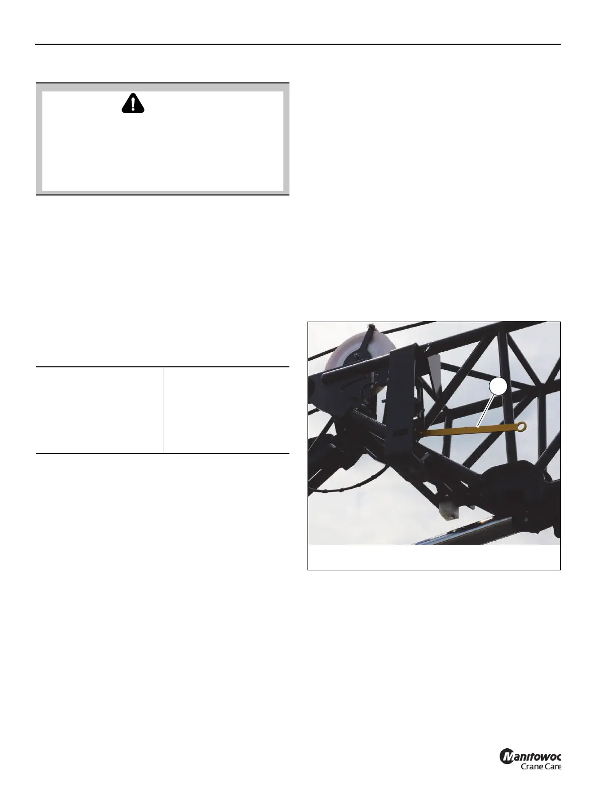
13. Raise the front mounting pin handle (1, Figure 5-40) to
unlock the boom extension installation pins.
DANGER
Boom Extension Hazard!
To avoid death or serious injury, follow procedures and
cautions in the Operator and Safety Manuals and decals
during erection, stowage and use of boom extension.
Install and secure all pins properly and control boom
extension movement at all times.
Required Tools
• 1/2 in Impact Wrench
• 24 in — 1/2 in Drive
Impact Extension
• 1/2 in Square Drive
Socket — 14 mm drive
6-point Socket
 Loading...


