MI 2893 / MI 2892 / MI 2885 Transient recorder
85
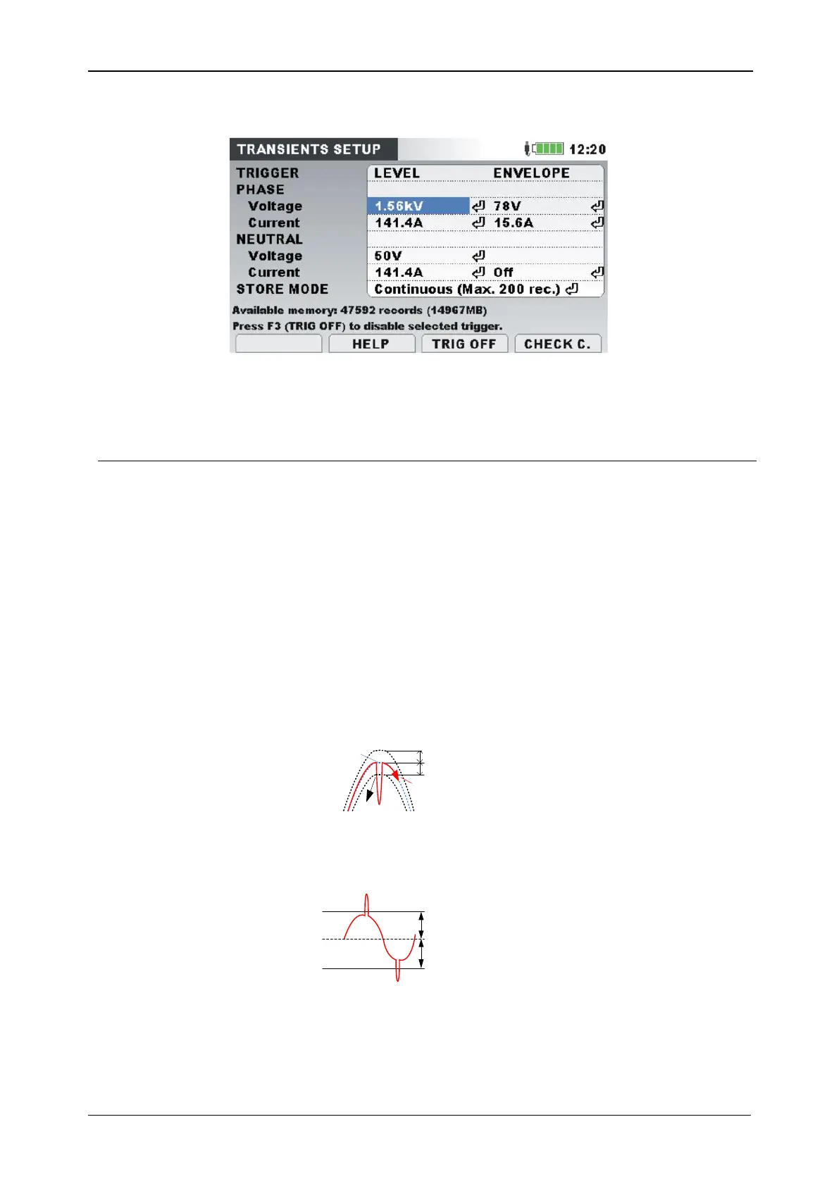
MAIN MENU RECORDERS TRANSIENT REC. F3 (SETUP)
Figure 63: Transient recorder setup screen – MI 2893
Table 64: Transient recorder settings description and screen symbols
Envelope: Trigger value is based on envelope within voltage/current
that is expected. As reference, voltage/current waveform from
previous cycle is taken. If current sample is not within envelope,
triggering will occur. See 5.1.20 for details.
Phase voltage limits:
Minimum value: 0.0055 * U
nom
* sqrt(2)
Maximum value: 1.1 * U
nom
* sqrt(2)
Neutral voltage limits not available
Phase/Neutral current limits:
Minimum value: 0.0055 * I
nom
* sqrt(2)
Maximum value: 1.1 * I
nom
* sqrt(2)
Envelope
Previous
cycle
Current
cycle
Trigger
Envelope
Level: Trigger will occur if any sample within period is greater than
defined absolute trigger level. Level is defined as absolute expected
monitoring value. See 5.1.20 for details.
Trigger level
Trigger level
Phase voltage limits:
Minimum value: U
nom
Maximum value: 5500 * VT ratio
Neutral voltage limits: