70
Pellerin Milnor Corporation
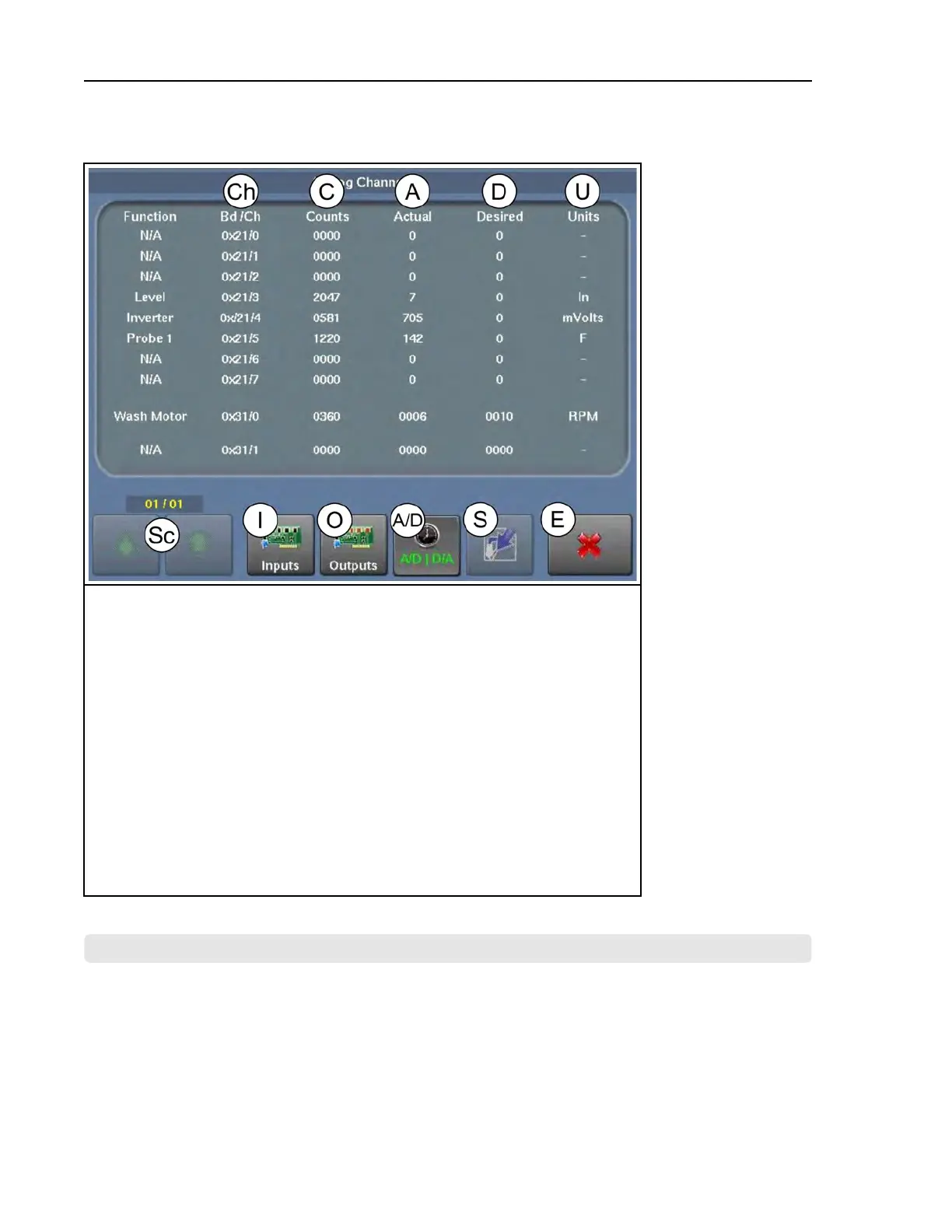
Figure 38. The Analog-Digital Values Display
Legend
A...The actual (current) value for the output for the input
A/D.View analog inputs and outputs (pictured)
C...(A/D) The digital counts value from the A/D converter used by the microproces-
sor to calculate the actual/desired units; (D/A) The digital counts value sent from
the microprocessor to the D/A converter that allows the proper voltage to be sent
to the inverter for motor control
Ch..The input/output circuit board and the input’s connection on that board
D...The desired value for the input
Ex..Exit (return to the Home display)
I...View the digital inputs
O...View the digital outputs
S...Spraydown, currently unavailable on WTB machines
Sc..Scroll between pages, if a view has more than one page
U...The units that quantify the values given in the “Actual” (A) and “Desired” (D)
columns
BNCLDT03 / 2020465
BNCLDT03 0000277551 A.3 11/12/20 1:43 PM Released
4.8 The MilTouch-EX™ WTB Input/Output Boards
BNCLDT01.C06 0000249604 E.2 A.3 A.4 1/2/20 1:22 PM Released
The input/output boards are typically located in the machine’s low-voltage control cabinet. Every
MilTouch-EX™ WTB machine can have a maximum of four 8-output 16-input boards and four
24-output boards. The machine will have whatever combination of boards is needed to handle all
digital outputs and inputs. Tags inside the cabinet door identify each board and the circuit func-
tions assigned to the numbered outputs and inputs (numbers printed next to the LEDs) on each
Troubleshooting