72
Pellerin Milnor Corporation
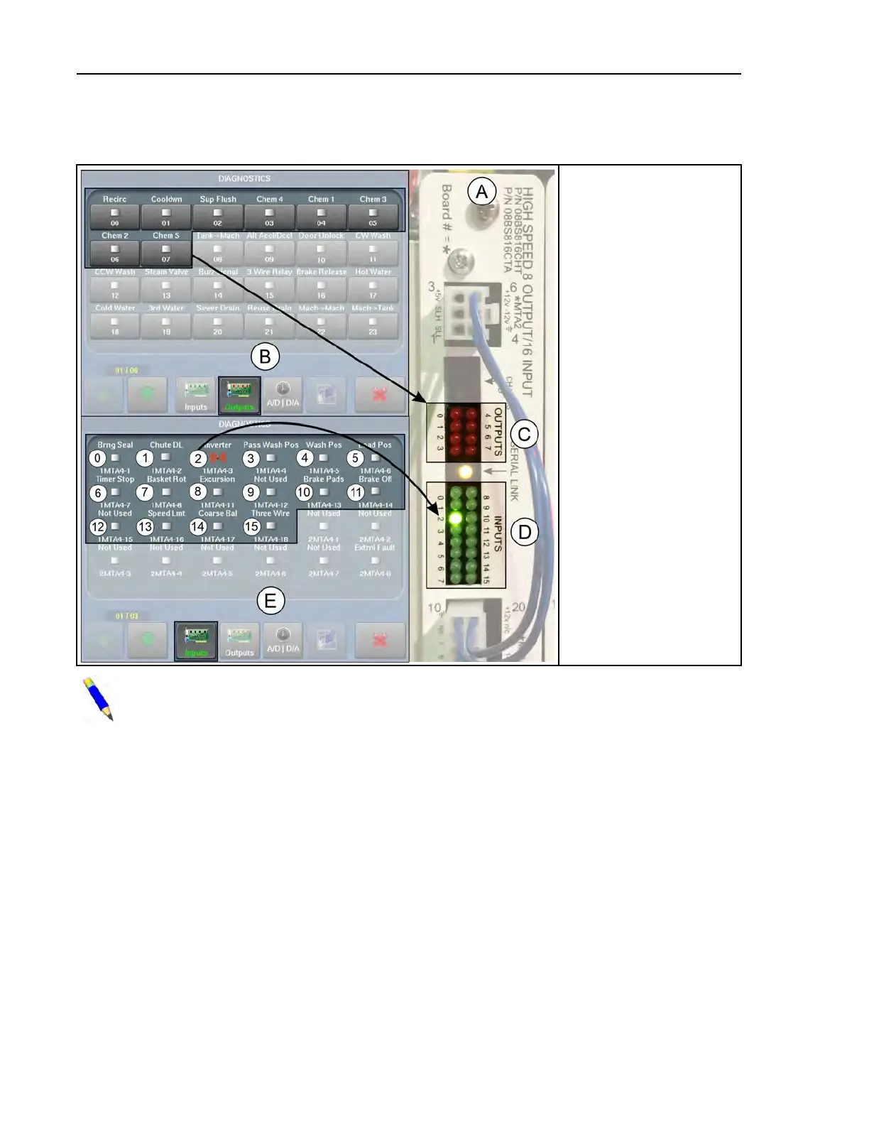
Figure 40. Input/Output Status Lights on the I/O Board and Corresponding Indicators on the
Diagnostics Display
Legend
A...8–Output 16–Input
Board 1
B... The Diagnostics dis-
play with Outputs
selected
C... Eight red LEDs (0–7)
— one per output. LED
illuminates when output
relay is energized.
D... Sixteen green LEDs
(0–15)— one per input.
LED illuminates when
input is actuated.
E... The Diagnostics dis-
play with Inputs
selected
0,1. . . Inputs labelled to
correspond with the
numbers printed next to
the LEDs on the board
NOTE: In the unlikely event that these indicators do not agree, there is a problem with
the controller. Contact Milnor
®
Customer Service/Technical Support using the contact in-
formation in Section 6.4 : How to Contact Milnor
®
, page 117.
4.8.2 How to Determine the Position of an Output or Input
BNCLDT01.C08 0000249776 E.2 A.3 1/2/20 1:22 PM Released
You cannot determine the position of an output or input on an I/O board from its position on the
Diagnostics display, or the reverse. Use the following information to determine which page/posi-
tion and board/LED the circuit to be checked corresponds to.
• The tables in Section 4.9 : List of Inputs and Outputs, page 74 are organized by board and list
the number (position) of each output and input on the boards and on the Diagnostics displays.
• The location of each board in the card cage is shown on a tag inside the electric box door (tag
also shown in schematic manual).
• Circuit logic, connector and pin numbers, wire numbers, etc. are provided in the schematic
manual.
Troubleshooting