2. CNC Monitor Screen
2.4 Parameters
I - 93
(Note) Selection of inch/metric unit
When setting value of "#1041 I_inch" is changed‚ the unit of length is changed after the power is
turned ON again.
Among parameters concerning length‚ following items are not changed automatically‚ therefore
change the setting values to match the new unit system when the unit system is changed.
Tool compensation amount (Tool length compensation amount‚ tool wear compensation amount
and tool nose compensation amount)
Workpiece coordinate offset
#8004 SPEED #8013 G83n
Machining
parameter
#8005 ZONE r #8016 G71 MINIMUM
#8006 ZONE d #8017 G71 DELTA-D
#8009 DSC. ZONE #8018 G84/G74n
#8010 ABS. MAX.
#8011 INC. MAX.
#8012 G73n
Axis parameter #8204 OT-CHECK-N
#8205 OT-CHECK-P
#8206 TOOL CHG.P
#8209 G60 SHIFT
Barrier data #8300 to #8306
Basic specification
parameter
#1084 RadErr
"#8004 SPEED" is 10 inches/min unit for the inch system.
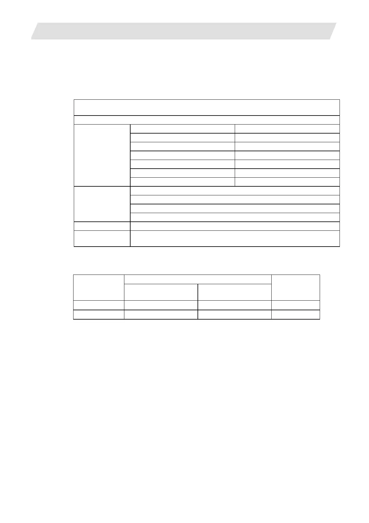
The parameter input setting units are as follows.
Linear axis "#1017 rot"=0
Input unit
"#1003 iunit"
Machine constant:mm
"#1040 M_inch"=0
Machine constant:inch
"#1040 M_inch"=1
Rotary axis
"#1017 rot"=1
B 0.001 mm 0.0001 inch 0.001°
C 0.0001 mm 0.00001 inch 0.0001°
 Loading...


