2. CNC Monitor Screen
2.3(II) Tool Offset (M system)
(Refer to "2.3 (I). Tool Offset (L system)" for Lathe system)
I - 71
2.3.1 Tool Offset
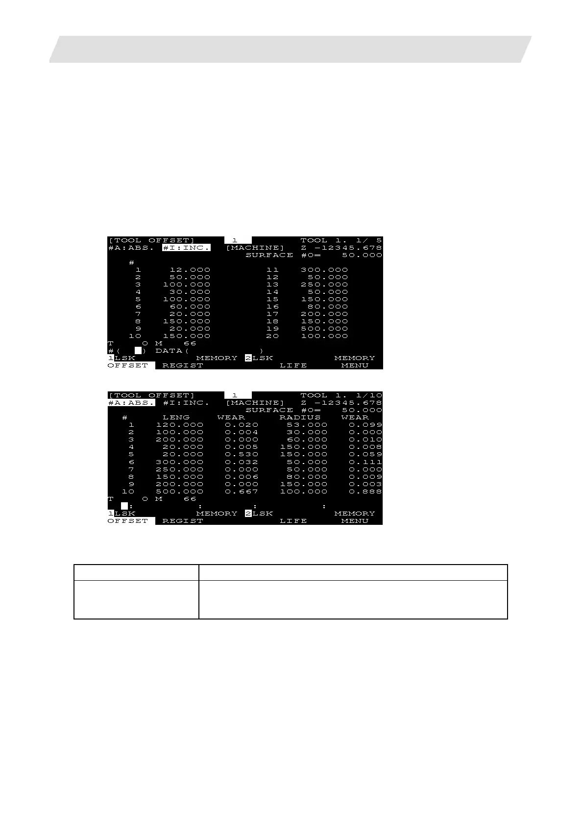
When the menu [OFFSET] is pressed, the TOOL OFFSET screen is displayed.
(1) Tool offset memory (type I: parameter "#1037 cmdtyp" = 1)
Form compensation memory is not distinct from abrasion compensation memory. Set the sum amount
of form compensation and abrasion compensation.
Offset data is common to the tool length, tool offset, tool diameter, and cutter compensation.
(2) Tool offset memory (type II: parameter "#1037 cmdtyp" = 2)
Set the shape compensation amount and wear compensation amount separately. The form
compensation amount is separated into the length dimensions and diameter dimension.
Of offset data, the length dimension data is used for tool length and the diameter dimension data is
used for tool diameter cutter compensation.
Tool offset memory type I
Tool offset memory type II
Tool offset data can be set in either absolute or incremental value.
Display item Description
#A: ABS #I: INC
The valid setting mode, either absolute or incremental mode, is
displayed in reverse video. Before setting data, check that the setting
mode is proper.
 Loading...


