2. CNC Monitor Screen
2.7 Diagnosis
I - 203
2.7.9.3 Address Designation
The followi
ng
three methods are available for setting the address: designating the prepared data with its
index No.; setting the actual address; searching for the head address of the symbol and set it automatically.
The applied method is automatically recognized.
A different designation method can be used for each address.
(Note) If the number of addresses exceeds the "#2 MARKS" value, the set address will be ignored.
(1) Index No. designation
The lower 6 digits of the 8-digit hexadecimal address are designated as index No.
The index No. is fixed regardless of the axis configuration.
The following shows how to set the lower 6 digits of address.
(No setting for the higher 2 digits is interpreted as "00".)
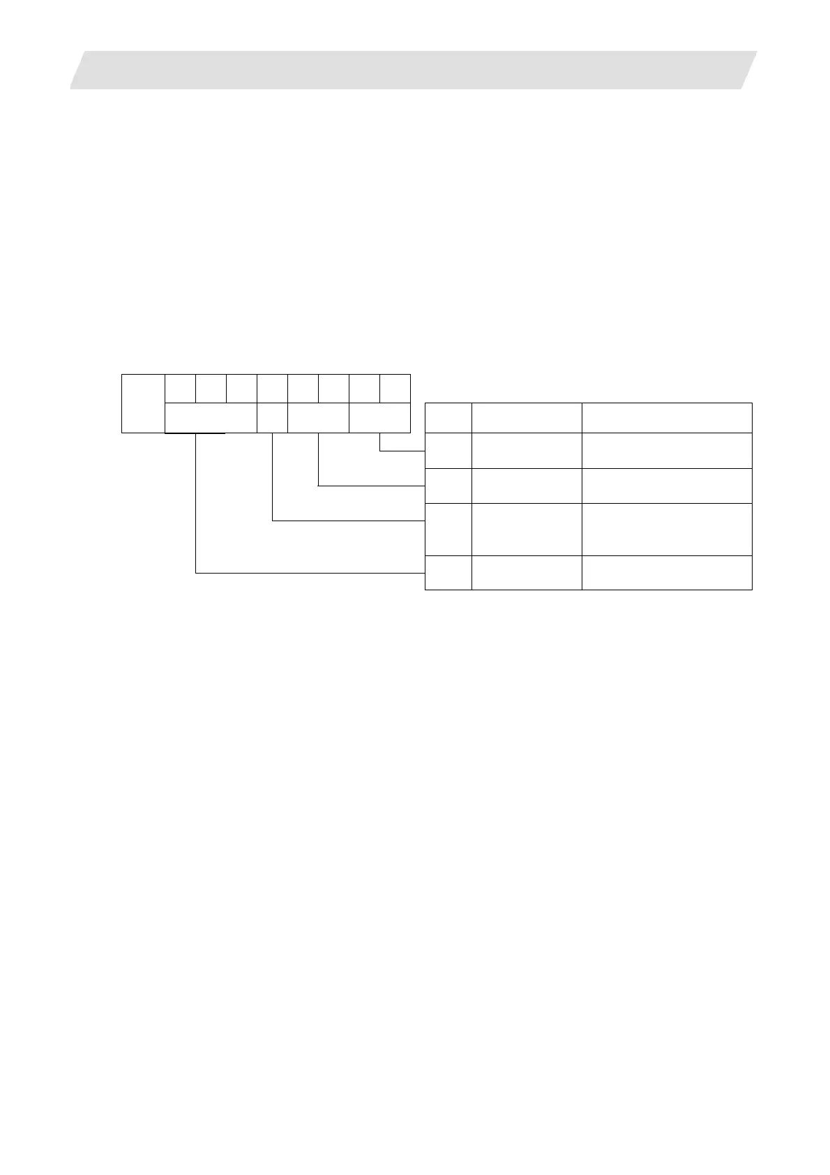
Allocation of digits is as follows.
Address
8 7 6 5 4 3 2 1
digit
digit Application Setting range
2,1 Target No.
Refer to "Target No.
List".
4,3 Servo axis No. 01 to 10 (in hexadecimal)
5 Spindle No.
1 to 7
8,7,6 Not used
"0" when the setting is
omitted
(Note1) In the following cases, the designated index No. will be treated as an illegal value and the sampling
will not be executed. (The sampled data will be "0".)
• When designated spindle No., servo axis No. or target No. was out of the setting range.
• When both spindle No. and servo axis No. were set.
• When a value except "0" was set in the unused part.
(Note 2) If the number of addresses set is more than the setting value for "#2 MARKS", it will be ignored.
 Loading...


