2. CNC Monitor Screen
2.7 Diagnosis
I - 204
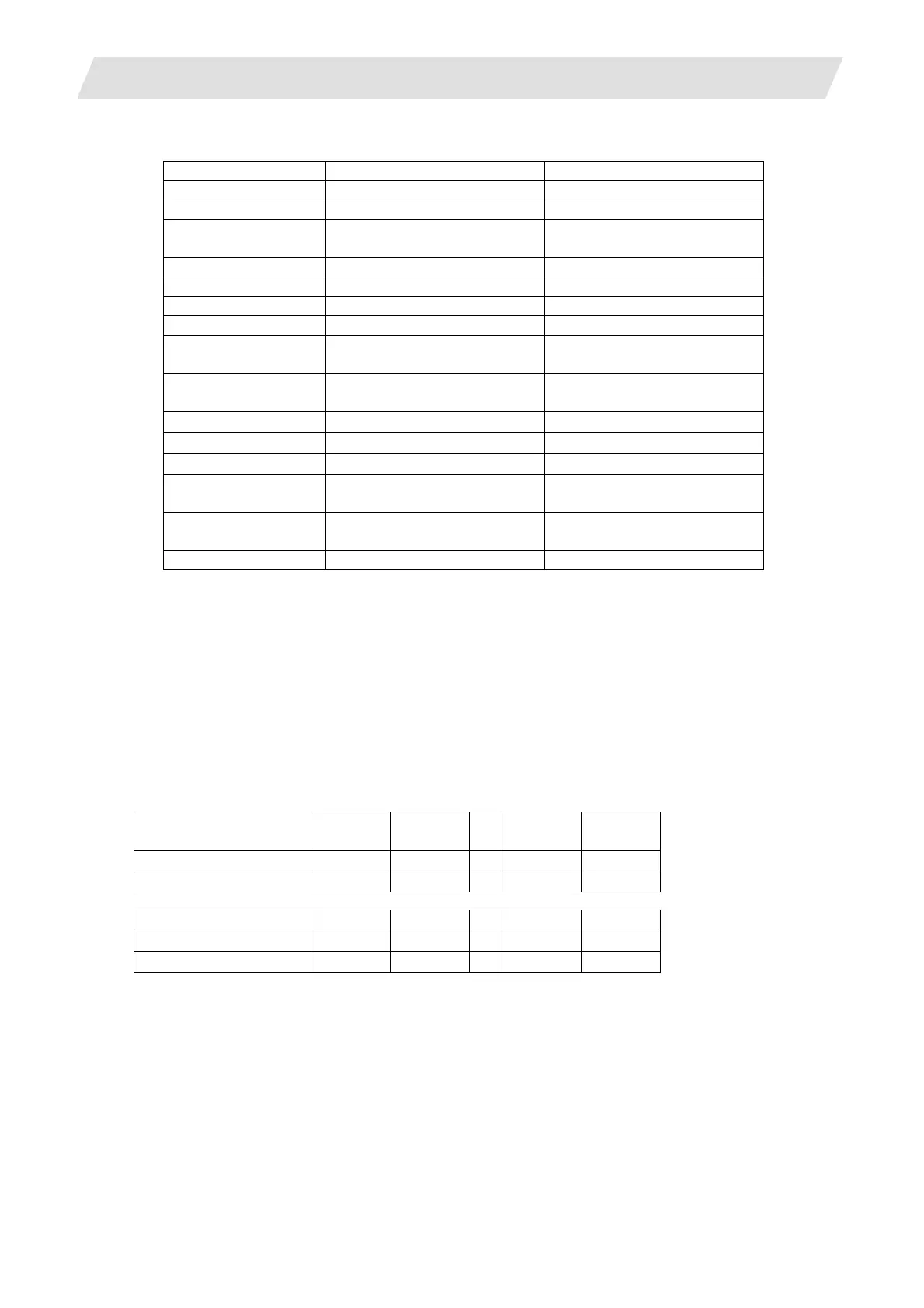
Target No. List (hexadecimal)
Target No. Servo axis, PLC axis Spindle
00 Position FB (Note 1) Position FB (Note 1)
01 Position command (Note 1) Position command (Note 1)
02 Number of motor rotations
(Note 2)
Number of motor rotations
(Note 2)
04 Load current (Note 3) Load current (Note 4)
06 Droop (Note 1) Droop (Note 1)
40 to 45 Control input 1 to 6 Control input 1 to 6
48 to 4D Control output 1 to 6 Control output 1 to 6
7E
-
Spindle position one rotation
data
7F
-
Spindle position FB one
rotation data
80
-
Cycle counter
81 Machine position
-
82
F
Δ
T
-
84
-
Synchronous tapping error
width
85
-
Synchronous tapping error
angle
86 Disturbance load torque Disturbance load torque
(Note 1) Position FB, position command, and droop are output as an interpolation unit.
EX) When "#1003 iunit" is B (1μµm) and output result is 2000:
20000 * 0.5 (interpolation unit) = 1000μm = 1mm
(Note 2) Output unit for the number of motor rotations is 0.01 r/min.
(Note 3) The same value as the load current displayed in the servo monitor screen is sampled for the load
current value of the servo and PLC axes. Output unit is %.
(Note 4) The same value as the load displayed in the spindle monitor screen is sampled for the load current
value of the spindle. Output unit is %.
Droop's sampling result is twice the value of a droop displayed in the servo/spindle monitor screen
of CNC monitor.
Setting example (of index No.)
Servo axis 1st axis 2nd axis
…
15th
axis
16th
axis
Feedback position
000100 000200
…
000F00 001000
Commanded position
000101 000201
…
000F01 001001
Spindle 1st axis 2nd axis
…
6th axis 7th axis
Feedback position
010000 020000
…
060000 070000
Commanded position
010001 020001
…
060001 070001
Setting examples for each purpose are shown below.
• For synchronized tapping: 3rd servo axis feedback (000300) - 1st spindle feedback (010000)
• For high-accuracy (roundness): 1st servo axis feedback (000100) - 2nd servo axis feedback (000200)
• For spindle synchronization: 1st spindle feedback (010000) - 2nd spindle feedback (020000)
 Loading...


