2. CNC Monitor Screen
I - 4
2. CNC Monitor Screen
In this screen, the various information which are needed to setup and maintain the machine and NC
system are displayed and set.
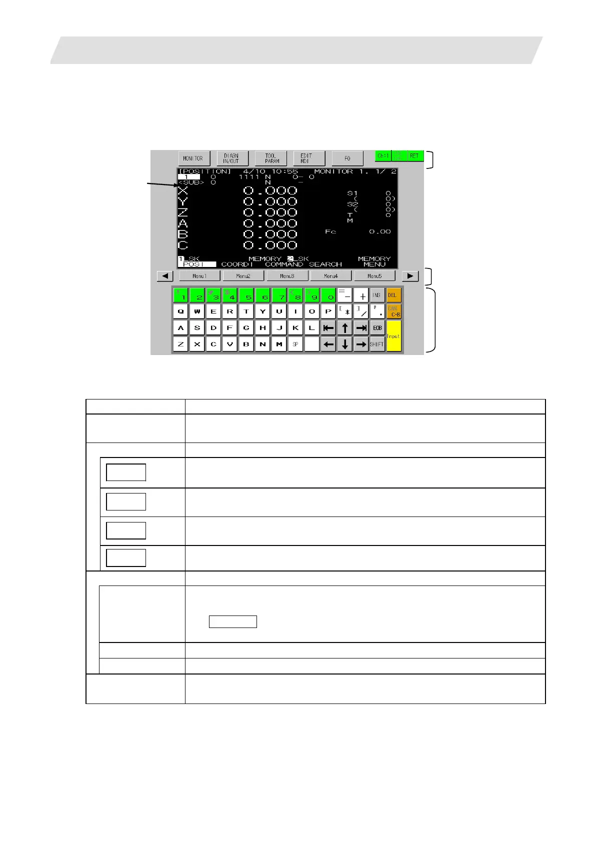
2. Function switch
3. Menu
4. Key board
1. NC screen area
(1) Display items
Display items Details
1. NC screen area The functions such as position monitoring, alarm diagnosis, tool
offset/parameters, and program edit.
2. Function switch The following keys used to select the display function.
MONITOR
Selects position monitoring function.
Refer to “2.2 Monitor”.
DIAGN
IN/OUT
Selects alarm diagnosis function or data input/output function.
Refer to “2.7 Diagnosis” and “2.6 Data In/Out.
TOOL
PARAM
Selects tool offset function and parameter setting. Refer to "2.3(I) Tool Offset(L
system)", "2.3(II) Tool Offset(M system)" and “2.4 Parameters”.
EDIT
MDI
Selects program edit function. Refer to “2.5 Program”.
3. Menu
MENU 1 to 5 Changes a screen according to menu.
If the NC-dedicated display is valid, the "KEY OPERATION INVALID" message
and OPERATE menu will appear.
Select this menu when operating the keys on the GOT.
BACK Displays the previous page if there are multiple pages in a screen.
NEXT Displays the next page if there are multiple pages in a screen.
4. Keyboard This is used to set a data in NC screens.
Refer to “(2) Composition of displayed keyboard“ for details.
 Loading...


