4. Operation Mode
4.4 Return to Reference Position Mode
II - 11
Operation procedure
MDI
MODE SELECT
MEMORY
RAPID
TRAVERSE
JOG
REFERENCE
POINT RETURN
HANDLE
INCRE-
MENTAL
25
100
50
1
%
RAPID TRAVERSE OVERRIDE
Dog
▲
Limit switch
Minus position
Plus position
Machine table
Minus
movement
-Reference point
X plus
coordinate system
Z plus
Spindle head
Plus
movement
The machine position depends on whether the near point detection limit switch is the plus or minus side
with the near point dog on the machine table as illustrated above as the reference.
When the limit switch exists on the dog, move to either plus or minus.
FEED AXIS SELECT
+X
-X
+Y
-Y
+Z
-Z
+4
-4
For dog mode return to reference position, turn on the FEED AXIS SELECT switch (+ or –) in the direction
where the dog and limit switch approach each other.
For high-speed reference point return, turn on the FEED AXIS SELECT switch (+ or –) in the direction that
the spindle head approaches the reference point.
Hold the FEED AXIS SELECT switch on during return to reference position until the machine passes by the
dog (dog mode) or the REFERENCE POSITION ARRIVAL lamp goes on (high speed return).
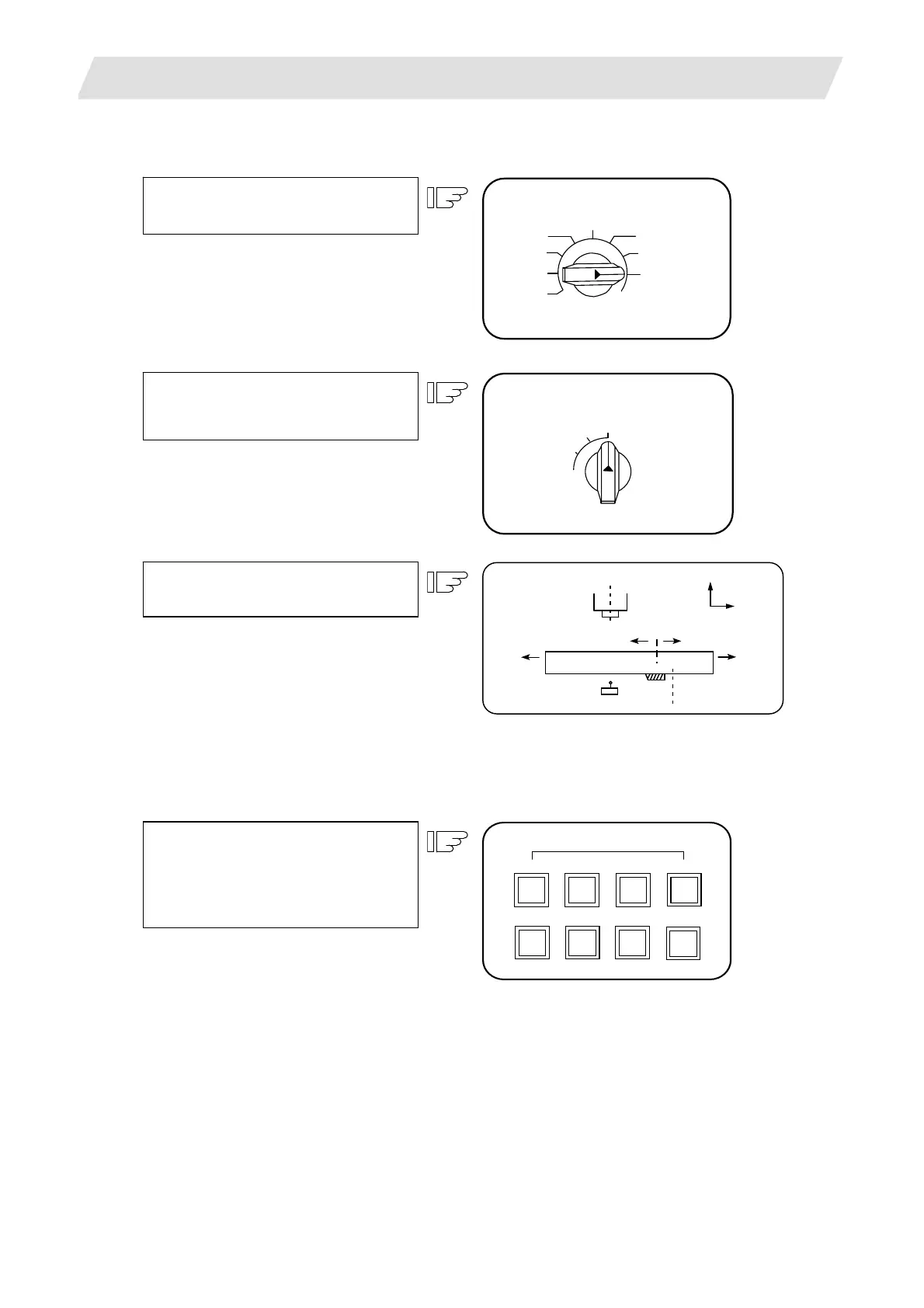
Check the current machine position.
Using the MODE SELECT switch,
select the return to reference position.
Using the RAPID TRAVERSE
OVERRIDE switch, set any desired
override value.
Using the FEED AXIS SELECT switch,
move the machine.
If the limit switch exists in the minus
direction as illustrated above, turn on a
plus FEED AXIS SELECT switch.
 Loading...


