2. CNC Monitor Screen
2.2 Monitor
I - 26
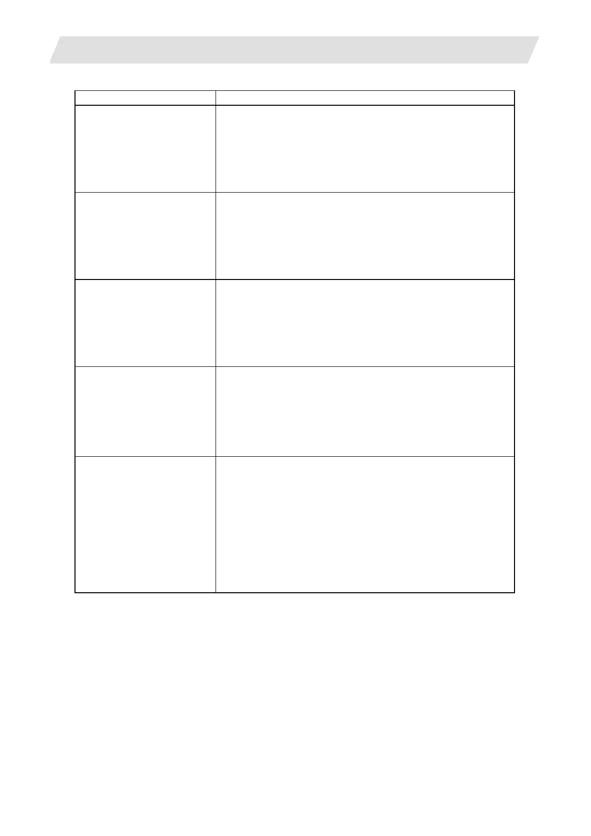
Display item Explanation
[WORK (G54)]
X 12345.000
Y 0.000
Z-12345.678
A 0.000
B 0.000
C 12345.678
G54 to G59 workpiece coordinate system modal numbers and the
coordinates in the workpiece coordinate system are displayed.
[MACHINE]
X 12345.000
Y 0.000
Z-12345.678
A 0.000
B 0.000
C 12345.678
The coordinates of each axis in the basic machine coordinate
system, in which the zero point is determined depending on the
machine, are displayed.
[DIS TO GO]
X 12345.000
Y 0.000
Z-12345.678
A 0.000
B 0.000
C 12345.678
The remaining distance of the move command being executed
(incremental distance from the current position to the end point of
the block) is displayed during automatic operation start busy or
pause busy.
[NEXT]
X
Y
Z
A
B
C
The coordinates of the end point in the block executed next are
displayed.
S1:0
:
The program command S modal value (maximum 7 sets) currently
being executed are displayed.
T 0
The program command T modal value currently being executed is
displayed.
M 66
:
The program command M modal values (maximum 4 sets)
currently being executed are displayed.
B
The program command 2nd miscellaneous function modal value
currently being executed is displayed.
 Loading...


