2. CNC Monitor Screen
2.3(I) Tool Offset (L system)
(Refer to "2.3 (II). Tool Offset (M system)" for Machining center system)
I - 52
(3) Explanation of operations
(a) Setting the tool compensation amount
1) Zero point return
After turning the power ON, establish the coordinate system by carrying out dog-type zero point return.
When using the absolute position detection specifications, carry out initialization if the absolute
position is not established.
2) Select the mode
Set the mode selection switch to the manual mode (either [handle], [jog] or [rapid traverse]).
3) Input the tool measurement mode signal
Set the tool measurement mode signal to "1".
The tool measurement mode is entered with steps 1), 2) and 3).
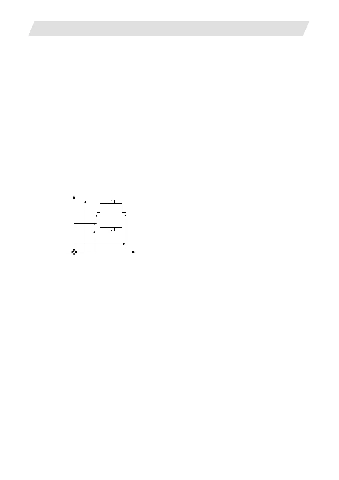
4) Confirm measurement base position (sensor position)
The following parameter must be set before carrying out tool setter operations.
#2015 tlml–, #2016 tlml+ (sensor position) Axis specification parameter p. 2
Z axis
X axis
Xm
Xp
Zm
Zp
Xm : X axis – sensor machine coordinate value (position measured by moving in – direction)
→ #2015 tlml– X axis
Zm : Z axis – sensor machine coordinate value (position measured by moving in – direction)
→ #2015 tlml– Z axis
Xp : X axis + sensor machine coordinate value (position measured by moving in + direction)
→ #2016 tlml+ X axis
Zp : Z axis + sensor machine coordinate value (position measured by moving in + direction)
→ #2016 tlml+ Z axis
5) Select the tool
Select the tool to be measured.
Set the compensation No. of the tool to be selected as a BCD code in R4720.
Set the compensation No. of the wear data to be cleared after measurement as a BCD code in R2431.
(The tool No. data is input from the PLC to the NC.)
 Loading...


