FX3U Series Programmable Controllers
User’s Manual - Hardware Edition
100
6 Examination of System Configuration
6.7 Expansion of Extension Power Supply Unit (FX3U-1PSU-5V)
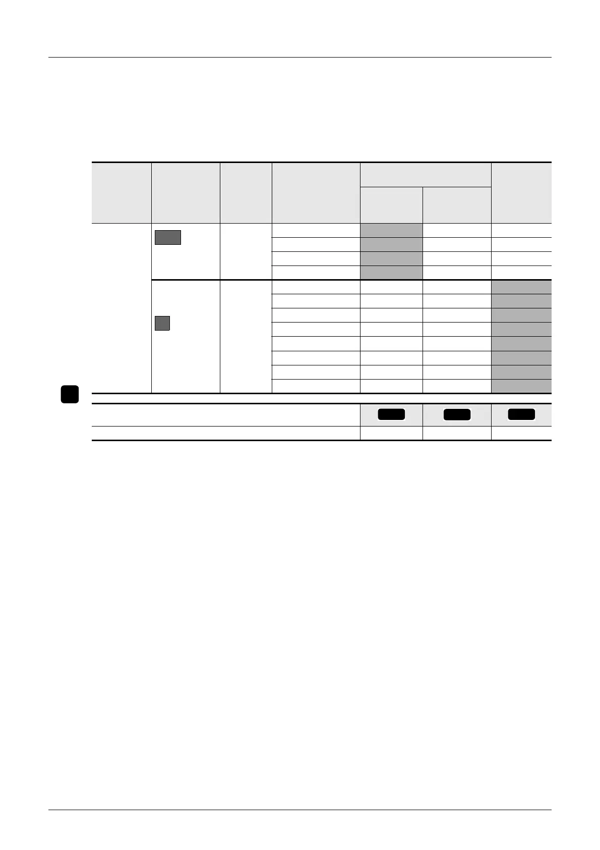
2 Enter the specifications for the products to be added.
Enter the data on the input/output extension blocks and special function units/blocks to be connected
to the input/output powered extension unit, and calculate the current.
→ For the data on the number of input/output occupied points and current consumption of each type,
refer to Section 6.8.
*1. Input/output occupied points by special function units/blocks are excluded.
*2. For input extension blocks (including FX
2N-8ER-ES/UL, FX2N-8ER), do not include the current
consumption by the internal 24V DC. Subtract the internal 24V DC current consumption from the
service power supply of the
input/output
powered extension unit or the nearest main unit on the
upstream side of extension power supply unit.
→ When the main unit is on the upstream side, refer to Subsection 6.5.1 and 6.5.2.
→ When the input/output powered extension unit is on the upstream side, refer to Subsection 6.6.1
and 6.6.2.
*3. A maximum of 8 special function units/blocks are connectable, including the main unit and the input/
output powered extension unit.
Power
supply
classification
Classification
Number of
connected
units
Type
Capacity of built-in power
supply
Number of
I/O occupied
points
*1
{points]
5V DC power
supply [mA]
Power supply
for internal
24V DC [mA]
Enter the
products
connected to
the extension
power supply
unit
Input/output
extension block
*2
−
FX
2N- −
FX
2N- −
FX
2N- −
FX
2N- −
Special function
unit/block
8
*3
FX0N/FX2N/FX3U- −
FX
0N/FX2N/FX3U- −
FX
0N/FX2N/FX3U- −
FX
0N/FX2N/FX3U- −
FX
0N/FX2N/FX3U- −
FX
0N/FX2N/FX3U- −
FX
0N/FX2N/FX3U- −
FX
0N/FX2N/FX3U- −
Calculate the totals
6
D2
E
6-
1
6-
2
6-
3

 Loading...


