7-16
Chapter 7 ASSEMBLY OF BASIC ENGINE
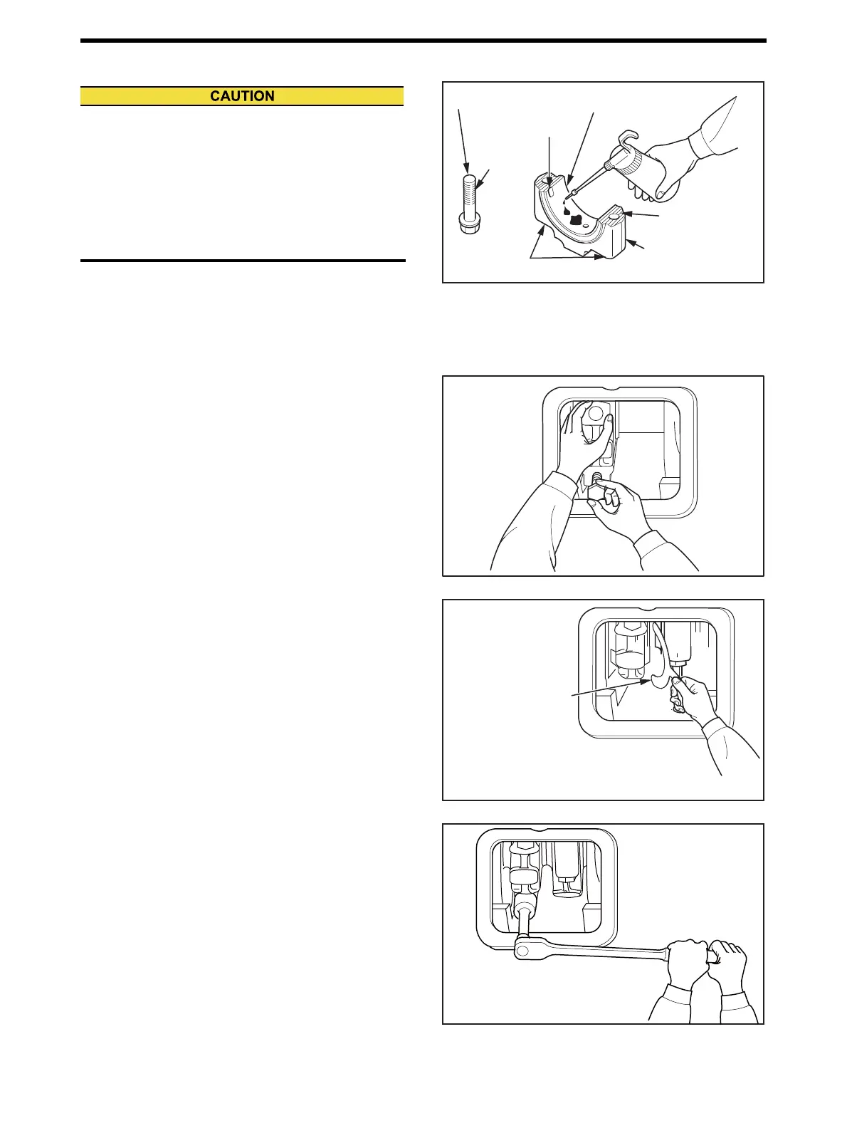
2.12 Connecting Rod Cap - Install
(1) Install the lower connecting rod bearing, aligning its
lug with the lug slot of the connecting rod bearing cap.
(2) Apply engine oil to the connecting rod bolt threads and
seating surface, and the sliding surface of the lower
connecting rod bearing shell.
Connecting Rod Cap - Install (1)
(3) Install the connecting rod cap to the connecting rod so
that that the matching numbers on the connecting rod
cap and the connecting rod are the same and on the
same side.
(4) Hand tighten the connecting rod bolts.
Connecting Rod Cap - Install (2)
(5) Align the connecting rod and rod cap side faces to
ensure the rod end play.
Note: To ensure the minimum end play, the connecting rod
gauge may be inserted between the two connecting
rods for adjustment.
(6) Measure the connecting rod end play, and adjust the
end play to the range of the standard value.
Connecting Rod Cap - Install (3)
(7) Tighten the connecting rod bolts to the specified
torque.After tightening to the specified torque, loosen
the bolts completely and tighten again to the specified
torque.(2-time tightening method)
Measure the end play again.
Note: To tighten the connecting rod bolts with the angle con-
trol tightening, follow the steps below.
(a)Tighten the bolt to a snug torque of 147±7.4 N•m
{15± 0.75kgf•m} [108±5.46 lbf•ft].
(b)Further rotate the bolt 45±3 degrees.
(c)Loosen all bolts, and then angle controlled tighten
them again.(2-time tightening method)
Connecting Rod Cap - Install (4)
(a) Make sure that the matching numbers on the con-
necting rod and the connecting rod cap are on the
same side and in alignment.
(b) When installing the connecting rod cap, make sure
that dust or metal particles are not caught in the
serrations, bolt seating surfaces and the bolt
threads.
Lug groove
Threaded
portion
Bolt's seat face
Lower connecting rod
bearing
Connecting rod bolt
Connecting rod cap
Serrated portion
P/N 0.5 mm [0.020 in.] : 32691-01500
0.6 mm [0.024 in.] : 32691-01600
Connecting rod gauge
Ensure the end play
with a connecting
rod gauge
343±17 N·m {35±1.8 kgf·m}
[148±13 lbf·ft] [Wet]
2 times tightening method

 Loading...