5-5
Chapter 5 DISASSEMBLY OF BASIC ENGINE
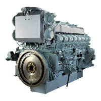
1.4 Fuel Injection Timing - Inspect
Inspect the fuel injection timing, and know the current con-
dition.
For the inspection procedures, refer to "Fuel Injection Tim-
ing - Check and Adjust" of "ASSEMBLY OF BASIC
ENGINE."
Fuel Injection Timing - Inspect
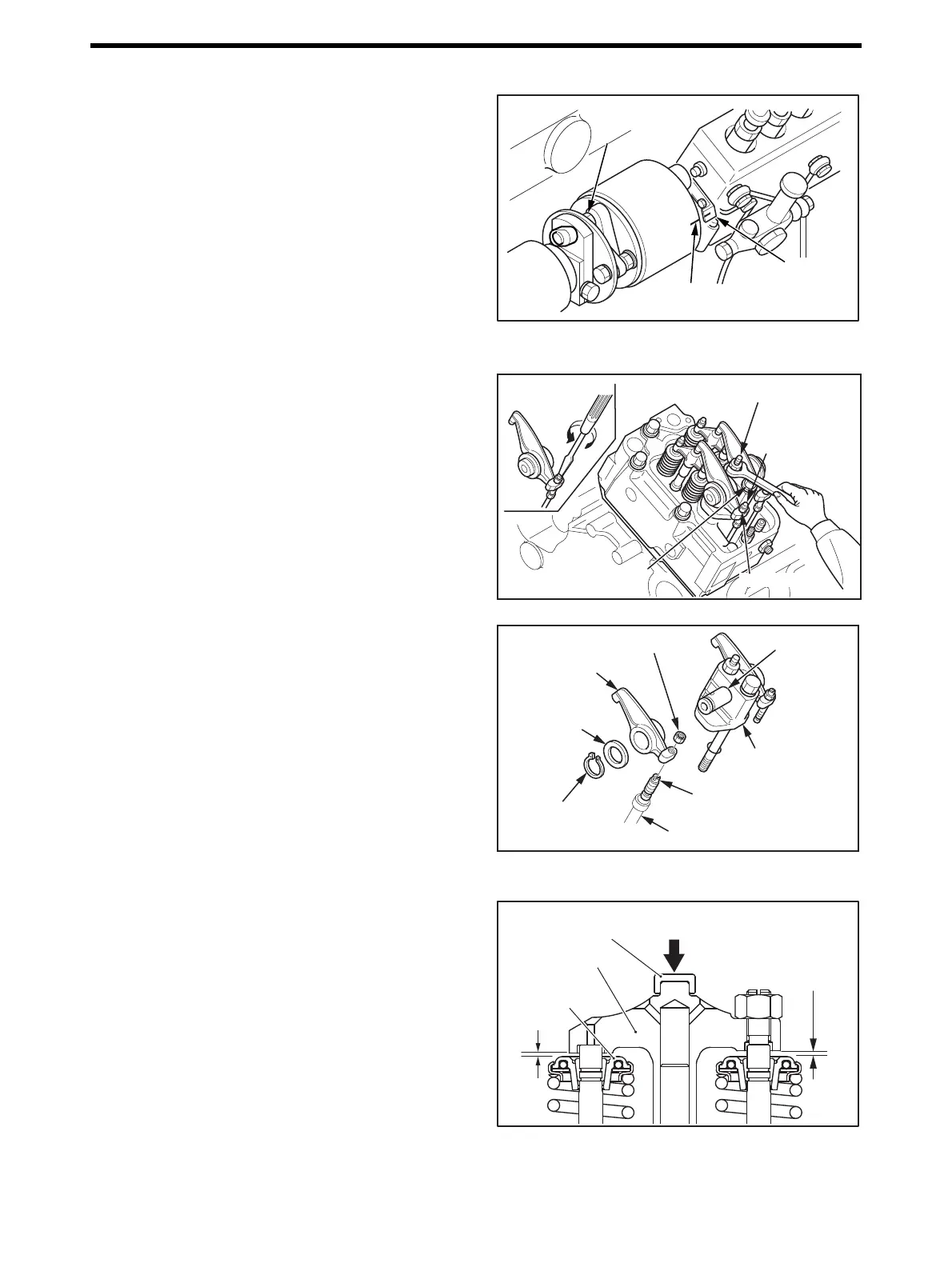
1.5 Rocker Shaft Assembly - Remove
(1) Loosen the adjusting screw of rocker arm.
(2) Remove the rocker bracket bolt.
(3) Remove the cylinder head bolt (long), which is also fix-
ing the rocker bracket.
(4) Remove the rocker shaft assembly from the cylinder
head.
Note: Keep the removed rocker shaft assembly and bolts as a
set.
Rocker Shaft Assembly - Remove
(5) Remove the push rod.
(6) Disassemble the rocker shaft assembly.
Note: Do not remove the rocker bushing unless it is defective
or its inside diameter exceeds the limit.
Rocker Shaft Assembly - Disassemble
1.6 Clearance Between Bottom Face of Valve Bridge and Top Face of Valve Rotator - Inspect
Inspect the clearance between the bottom face of valve
bridge and the top face of valve rotator, and know the cur-
rent condition.
For the inspection procedure, refer to "Clearance Between
Bottom Face of Valve Bridge and Top Face of Valve Rota-
tor - Measure" of "ASSEMBLY OF BASIC ENGINE."
Clearance Between Bottom Face of Valve Bridge and
Top Face of Valve Rotator - Inspect
88 ± 5 N·m
{9 ± 0.5 kgf·m}
[65 ± 3.7 lbf·ft]
Fuel injection pump
coupling (punch) mark
Pointer
88 ± 5 N·m
{9 ± 0.5 kgf·m}
[65 ± 3.7 lbf·ft]
Cylinder head bolt
(long)
Rocker bracket bolt
Loosen
Lock nut
Adjusting screw
Cylinder head bolt
(long)
Rocker shaft
Rocker shaft
bracket
Adjusting screw
Snap ring
Washer
Lock nut
Rocker arm
Push rod
Hold down the top
of bridge by hand.
Clearance between
valve bridge bottom
face and valve
rotator top face
Valve rotator
Bridge cap
Valve bridge

 Loading...