8-39
Chapter 8 FUEL SYSTEM
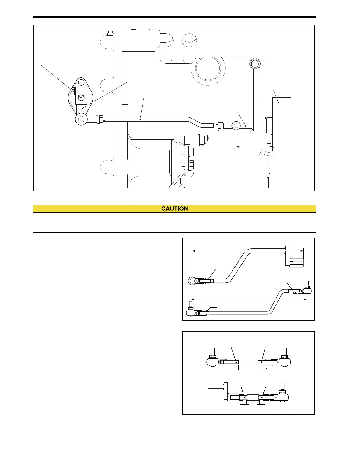
Right-bank linkage - Overall view
Common
(1) Install the fixed-length (304±1.0 mm [12±0.04 in.])
control link A-1 in between the fuel injection pump
control rack and the control lever on the right bank.
PSG type governor spec
(2) Adjust the variable-length control link B-1 on the left
bank to 95.5 mm [3.76 in.], and tentatively tighten it.
Then fix it to the fixed-length (208.5±1.0 mm
[8.21±0.04 in.]) control link A-2.
(3) Assemble the variable-length control link B-1 into the
stop lever having a serrated hole. Install the fixed-
length (208.5±1.0 mm [8.21±0.04 in.]) control link A-2
to the fuel injection pump control rack.
Check that the fuel injection pump racks of both banks
are at the no-injection position, then install the stop
lever together with the spacer and cancel spring to the
serration on the control shaft.
Note: Adjust the engagement lengths even on right and left-
handed threads.
(4) Fine adjust the variable-length control link B-1 for the
left bank so that movement of the fuel injection pump
rack becomes the same on both banks.
Fixed-length control links of right and left banks
Left bank variable-length control link
Distance between the end face of fuel injection pump
Distance between the end face of fuel injection pump
and the center of hole at control rack end: 78 mm [3.07 in.]
and the center of hole at control rack end: 78 mm [3.07 in.]
Control rack position
Control rack position 「0」
: 67.5mm [2.99 in.]
Play: approx. 2 mm [0.08 in.]
Play: approx. 2 mm [0.08 in.]
Control rack
Fuel injection pump
Control shaft
Control lever
Woodward PSG governor spec
Toho Seisakusho SG4017 actuator spec
Fixed length
(304 ± 1.0 mm [11.97 ± 0.0394 in.])control rink A-1
Distance between the end face of fuel injection pump
and the center of hole at control rack end: 78 mm [3.07 in.]
Control rack position 「0」: 67.5mm [2.99 in.]
Play: approx. 2 mm [0.08 in.]
If the play of fuel injection pump rack is in excess, fuel can not be stopped even when the governor brings the link to
engine stop position, and engine over-running may results.
Left bank fixed length control link
Right bank fixed length control link
Welding
Welding
Welding
304 ± 1.0 mm [11.97 ± 0.039 in.]
208.5 ± 1.0 mm
[8.209 ± 0.039 in.]
Left bank variable length control link
Left-hand thread
Right-hand thread
Left-hand
thread
Right-hand
thread
Make the length of engagements even.
Make the length of engagements even.

 Loading...