8-40
Chapter 8 FUEL SYSTEM
(5) Adjust the variable-length control link B-2 to 158±1.5
mm [6.2±0.06 in.], and install it in between the control
lever and the governor lever.
Fine adjust so that the distance between fuel injection
pump end face and the center of hole at the end of rack
becomes 67.5 mm [2.66 in.] with 2mm [0.079 in.] play
when the governor output shaft is at zero (no injection).
Note: Insert the reverse threaded portions of the variable-
length link, right and left equally, so that the length of
thread engagement becomes 10mm [0.39] or more.
(6) Make sure that the distance between the center of hole
locating at the end of fuel injection pump rack and the
fuel injection pump end face is 6735 mm [2.66 in.] with
a 2mm [0.08 in.] play when the stop lever is fully
pulled to the stop side (rack "0" position).
SG4017 type actuator spec
(2) Assemble the variable-length control link B-3 on the
left bank to the fixed-length (208.5±1.0 mm [8.21±0.04
in.]) control link A-3.
(3) Assemble the variable-length control link B-3 into the
stop lever having a serrated hole. Install the fixed-
length (208.5±1.0 mm [8.21±0.04 in.]) control link A-3
to the fuel injection pump control rack.
Check that the fuel injection pump racks of both banks
are at the no-injection position, then install the stop
lever together with the spacer and cancel spring to the
serration on the control shaft.
Note: Adjust the engagement lengths even on right and left-
handed threads.
(4) Fine adjust the variable-length control link B-3 for the
left bank so that movement of the fuel injection pump
rack becomes the same on both banks.
(5) Install the variable-length control link B-4 between the
control lever and the governor lever.
The installing angle of governor lever must be 25º to
the variable-length control link B-4.
Fine adjust so that the distance between fuel injection
pump end face and the center of hole at the end of rack
becomes 67.5 mm [2.66 in.] with 2mm [0.079 in.] play
when the governor output shaft is at zero (no injection).
Note: Insert the reverse threaded portions of the variable-
length link, right and left equally, so that the length of
thread engagement becomes 10mm [0.39] or more.
(6) Make sure that the distance between the center of hole
locating at the end of fuel injection pump rack and the
fuel injection pump end face is 6735 mm [2.66 in.] with
a 2mm [0.08 in.] play when the stop lever is fully
pulled to the stop side (rack "0" position).
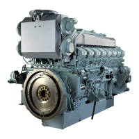
Fixed-length control links of right and left banks
Left bank variable-length control link
Left bank fixed length control link
Right bank fixed length control link
Welding
Welding
Welding
304 ± 1.0 mm [11.97 ± 0.039 in.]
208.5 ± 1.0 mm
[8.209 ± 0.039 in.]
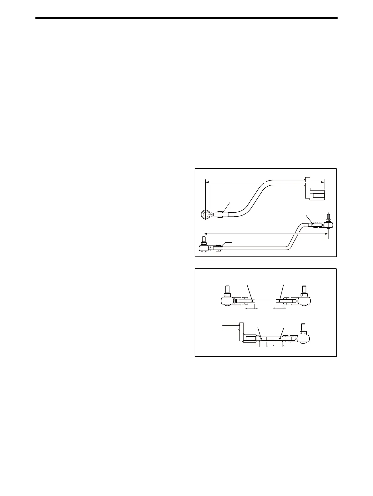
Left bank variable length control link
Left-hand thread
Right-hand thread
Left-hand
thread
Right-hand
thread
Make the length of engagements even.
Make the length of engagements even.

 Loading...