7-24
Chapter 7 ASSEMBLY OF BASIC ENGINE
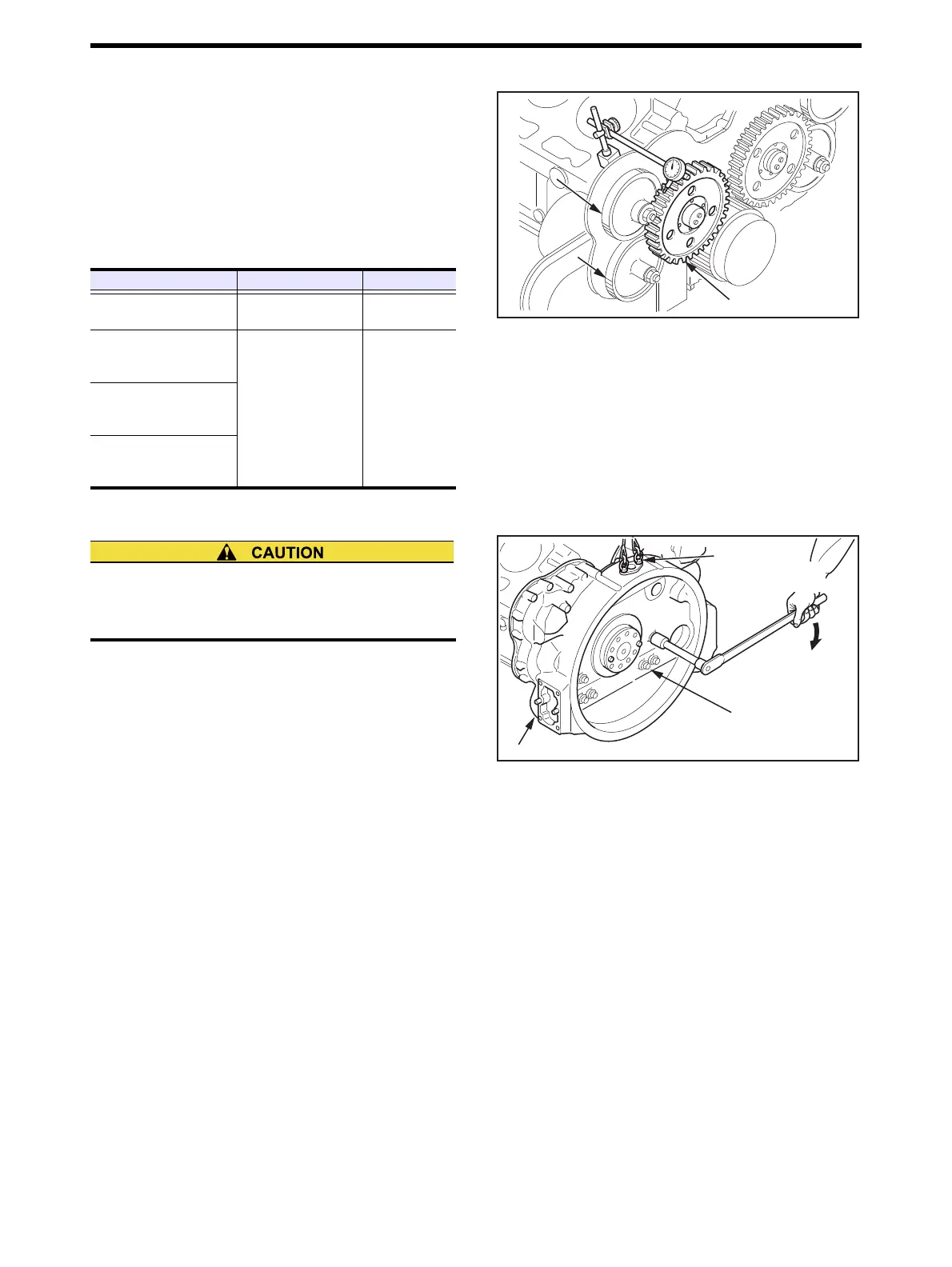
4.10 Timing Gear Backlash - Measure
Measure the backlash of timing gears using either method:
measure the gear backlash with a dial gauge applying its
probe to a tooth flank on the pitch circle at a right angle to
the tooth axis, or measure the clearance between gears by
inserting thickness gauges between the engaging gear
teeth.If the value exceeds the limit, replace the gears with
new ones.
Timing Gear Backlash - Measure
4.11 Timing Gear Case - Install
(1) Apply sealant (ThreeBond 1211) to the rare plate pack-
ing mating surface, and install the packing.
(2) Apply sealant (ThreeBond 1211) to the packing mating
surface to timing gear case.
(3) Set the eye bolt to timing gear case, align it with the
dowel pins, and install the timing gear case.
(4) Tighten the bolts to the specified torque.
(5) Cut off excessive packing carefully from the bottom of
crankcase.
Timing Gear Case - Install
Item Standard value Limit value
Backlash between crank
gear and idler gear
0.11 to 0.25 mm
[0.0043 to 0.0098 in.]
0.50 mm
[0.0197 in.]
Backlash between fuel
injection pump gear and
camshaft gear
0.12 to 0.18 mm
[0.0047 to 0.0071 in.]
0.50 mm
[0.0197 in.]
Backlash between idler
gear and fuel injection
pump gear
Backlash between crank-
shaft gear and oil pump
gear
Camshaft gear
Fuel injection
pump gear
Idler gear
Camshaft gear
Fuel injection
pump gear
Be careful not to drop or bump the timing gear case.It
will result in personnel injury as well as damage of the
timing gear case.
Timing gear case
M12:
98
±
4.9 N
{10
±
0.5 kgf
m}
[72.3
3.61 lbf
tt]
M16:
255
±
12.8 N
{26
±
1.3 kgf
m}
[188.1
9.44 lbf
ft]
Eyebolt
P/N:05930-00200
(M12 × 1.25 mm)
M12:
98 ± 4.9 N·m
{10 ± 0.5 kgf·m}
[72.3 ± 3.61 lbf·tt]
M16:
255 ± 12.8 N·m
{26 ± 1.3 kgf·m}
[188.1 ± 9.44 lbf·ft]

 Loading...