8-43
Chapter 8 FUEL SYSTEM
(5) Install the variable-length control link B-1 for the left
bank C between the control lever and the governor
lever.
Fine adjust so that the distance between fuel injection
pump end face and the center of hole at the end of rack
becomes 67.5 mm [2.66 in.] with 2mm [0.079 in.] play
when the angle scale of actuator output shaft is at zero
(no injection).
Note: Adjust the engagement lengths even and 8 mm [0.32
in.] or more on right and left-handed threads of the
variable-length control link.
(6) Make sure that the distance between the center of hole
locating at the end of fuel injection pump rack and the
fuel injection pump end face is 6735 mm [2.66 in.] with
a 2mm [0.08 in.] play when the stop lever is fully
pulled to the stop side (rack "0" position).
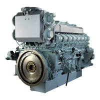
Woodward PROACT type actuator spec only
Stopper - Install
Install the stopper bolt to the plate.
When the actuator output shaft angle scale reads "0" (no
injection), screw the stopper bolt until it comes into contact
with the top face of the governor lever.
Governor actuator output shaft - Angle scale
Governor lever stopper - Adjust
Zero scale mark
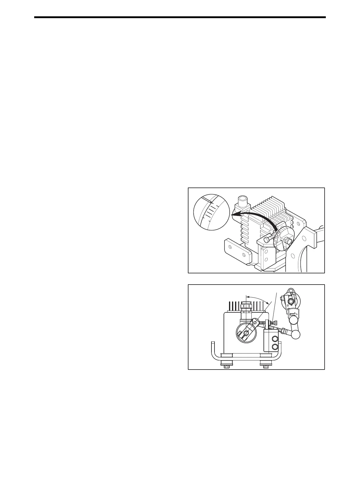
STOP
39.7°
Stopper bolt

 Loading...