No. 99MBB091A
4 - 4
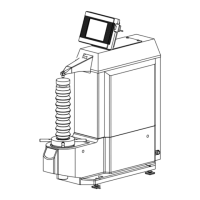
2. Attach a support foot to the rear of the Drive unit as shown.
3. Level the Drive/Detector unit by adjusting the foot height.
TIP For information about adjusting the support foot height, refer to “Chapter 10 IN-
STALLING THE SJ-301 WITH OPTIONAL ACCESSORIES ■ Support feet”.
Support feet
Precision roughness
specimen
Adjust the heights so that the Detector is parallel
to the measured surface.
4. Set the SJ-301 so that the Detector traversing direction is perpendicular to the cutter mark
of the precision roughness specimen.
Top view
Precision roughness specimen
 Loading...