SECTION 5
DISASSEMBLY AND ASSEMBLY
102
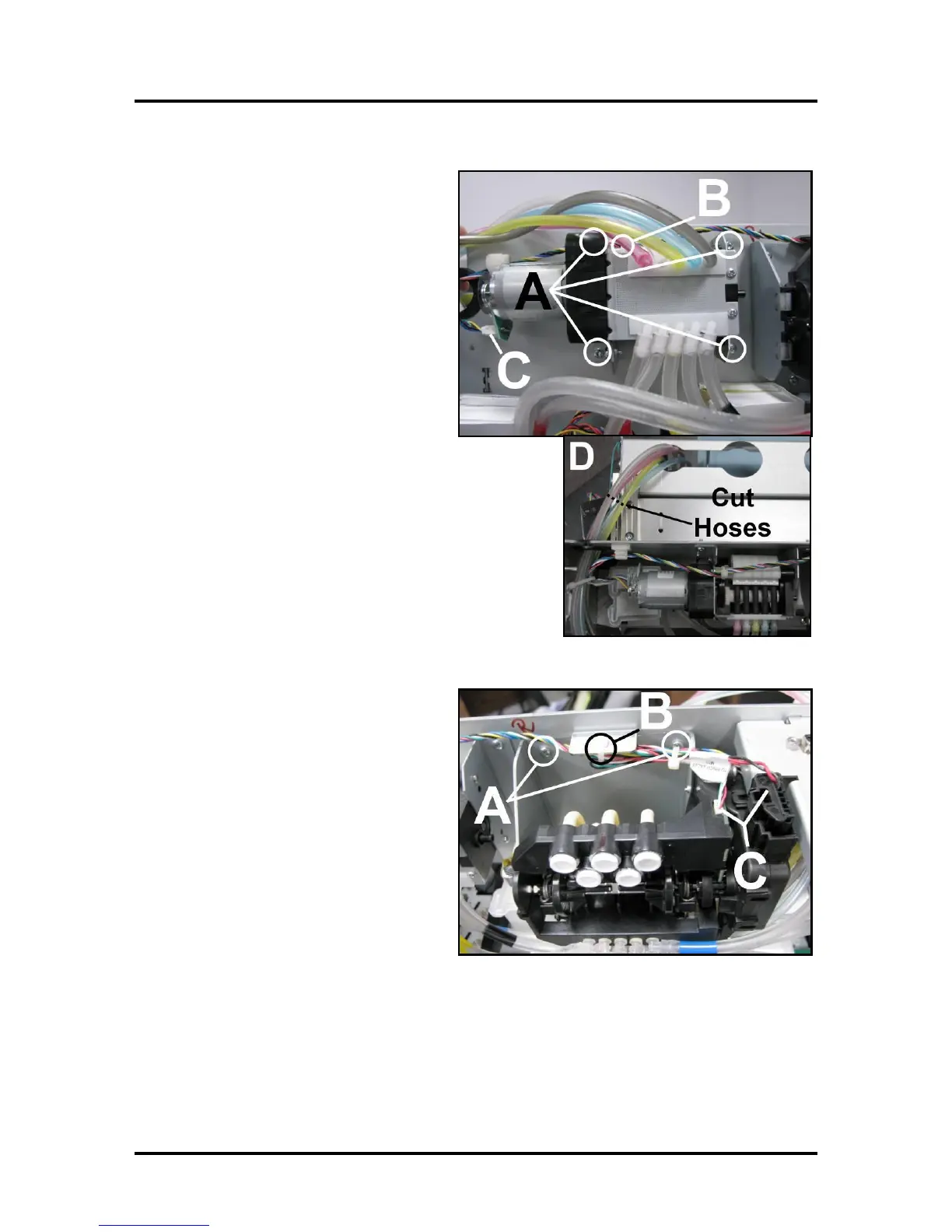
Replacing Peristaltic Pump Assembly
Remove old Pump Assembly:
[A] Remove (4) screws that hold bracket to
chassis.
[B] Cut cable tie holding wiring harness to
Assembly.
[C] Unplug connector from pump motor
circuit board.
[D] Cut as shown or remove hoses from
barbs. IMPORTANT! Make sure you
know where each ink hose connects.
Remove old Pump Assembly.
Install new Pump Assembly:
Plug wire connector into new Pump Assembly Motor circuit
board [C].
Attach to chassis with (4) screws [A].
Cable tie wire harness to assembly as shown in Step 1 [B].
Attach ink hoses in order shown to hose splice connectors
(included with kit) [D].
IMPORTANT! Make sure you know where each ink hose
connects for reassembly.
Replacing Dual Pinch Valve Assembly
Remove old Valve Assembly:
[A] Remove (4) screws that hold bracket to
chassis.
[B] Cut cable tie holding wiring harness to
top flange on Bracket Assembly.
[C] Unplug the (2) connectors from the
Valve Assembly.
[D] Disconnect ink hoses. IMPORTANT!
Make sure you know where each ink hose
connects.
Remove old Pinch Valve Assembly.
Install new Pinch Valve Assembly:
Plug wire connectors into new Pinch Valve Assembly [C].
Attach to chassis with (4) screws [A].
Cable tie wire harness to top flange on Pinch Valve Assembly as shown in Step 1 [B].
Reattach Ink Hoses in to same connector they were removed from. NOTE: Check that Hoses were
not stretched or damaged when they were disconnected. If damaged, or you have any doubt, cut
the damaged or stretched portion off before installing.

 Loading...

