SECTION 4
MEASUREMENTS & ADJUSTMENTS
45
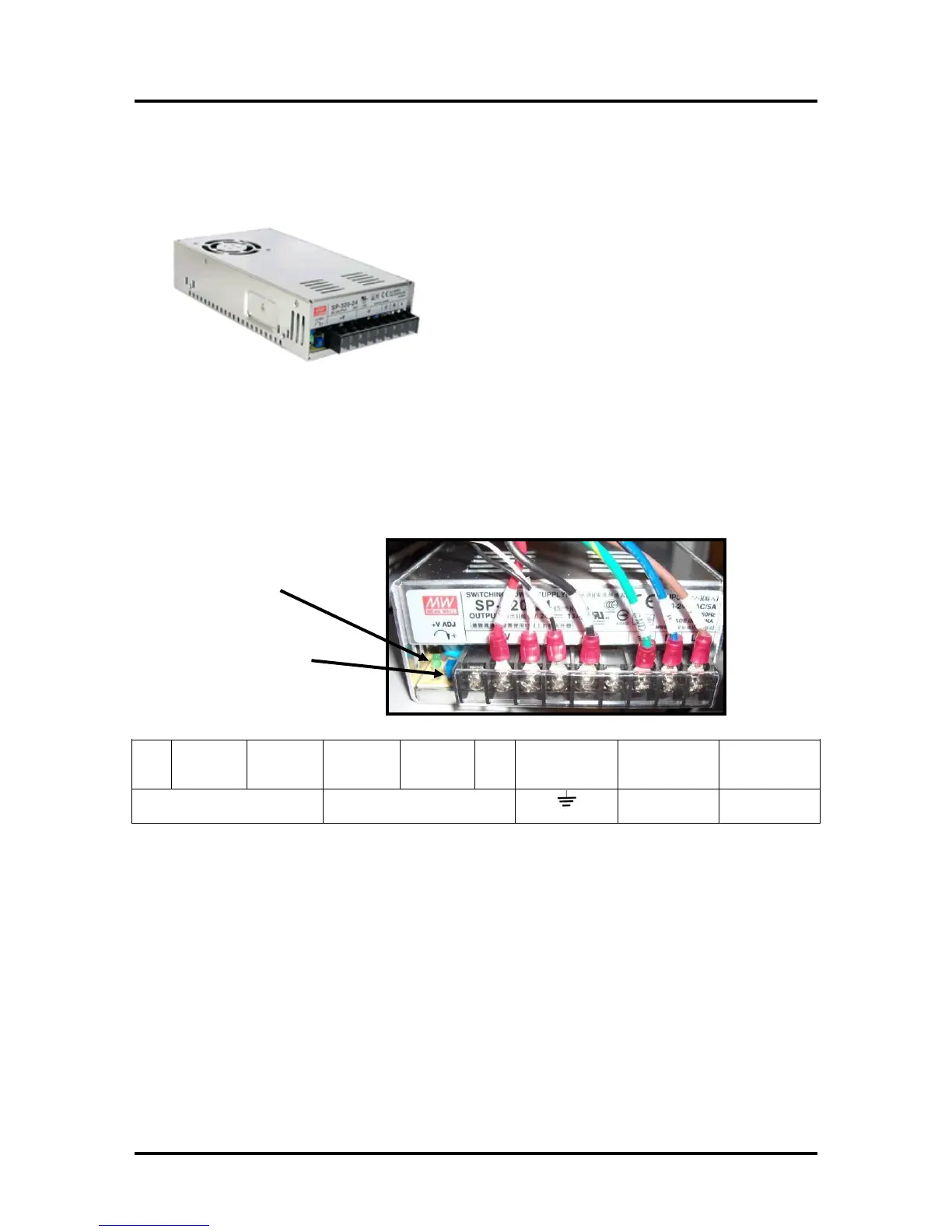
Power Supply
The Power supply converts the incoming AC voltage into 24 VDC.
The DC output provides power to the electronics for the entire printer.
Power Supply Measurements:
Input: 100 – 240 VAC (This is an auto-switching power supply)
Output: 24 VDC (+ or – 0.2 VDC)
Adjustment: There is normally no need to adjust the power supply output. However, if the voltage
reading is out of the tolerance range; an adjustment can be done using the +V Adjustment Pot shown in
the image below.
Connections:
Green/Yellow
to Frame
Ground
Troubleshooting Tip: If you don’t get any DC output (measuring 0 VDC and Power Indicator light is
off); check the AC Input to the power supply.
If you have proper AC input, but no DC output, then the power supply may be bad. Test the supply
with the output connections disconnected, to be sure nothing is shorting-out the supply. Cycle power
before re-testing.
If you don’t measure a proper AC input (110-240 VAC) then you may have a blown fuse in the
receptacle, a bad receptacle (check to be sure switch is ON), or no power from wall outlet.

 Loading...

