SECTION 5
DISASSEMBLY AND ASSEMBLY
104
Replacing Dual Pinch Valve Sensor PC Board
The Dual Pinch Valve Sensor PC Board Replacement Kit (42-900-85) includes a new Sensor Printed
Circuit Board, three (3) metal Inserts and a Pinch Valve Wrench.
Remove the Dual Pinch Valve Assembly.
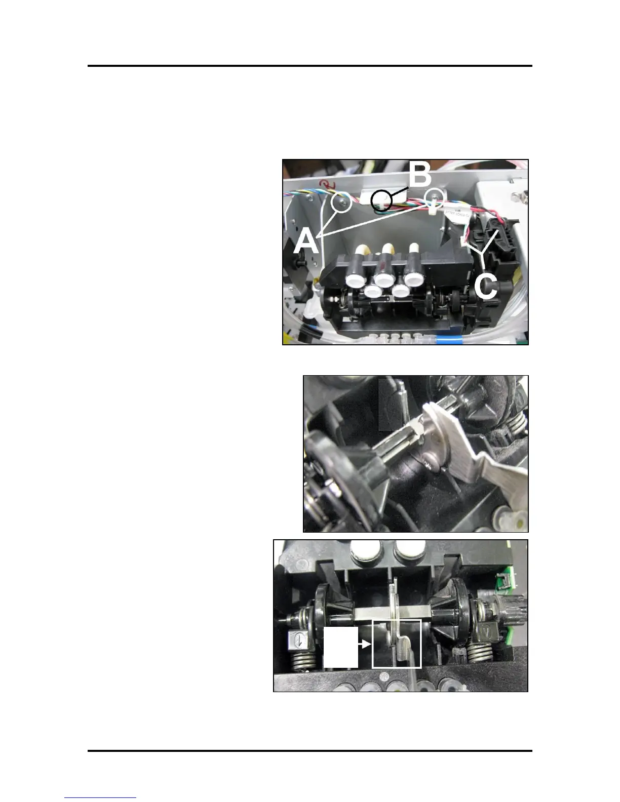
[A] Remove (4) screws that hold
Bracket to Chassis.
[B] Cut cable tie holding wiring harness
to top flange on Bracket Assembly.
[C] Unplug the (2) connectors from the
Valve Assembly.
IMPORTANT! Ink hoses are still
attached. Carefully pull Pinch Valve
Assembly away from chassis without
kinking or pulling out hoses.
Sensor Board Replacement Procedure
1. Secure the spring-loaded shaft using
the Dual Pinch Valve Wrench included
in Kit. Position the wrench exactly as
shown.
The Pinch Valve Wrench holds the
spring-loaded Pinch Valve Shaft in
alignment while the Motor Assembly is
detached from the Valve Body.
NOTE: The Wrench fits around
the shaft as shown. Please be
sure that the Wrench head and
the screw head [D] fit around the
Pinch Valve housing Rib; as
shown.
IMPORTANT! Make sure the
Wrench is positioned correctly
before proceeding. If this step is
not done correctly; damage to the
Sensors on the Dual Pinch Valve
Sensor PC Board may result.

 Loading...

