SECTION 5
DISASSEMBLY AND ASSEMBLY
105
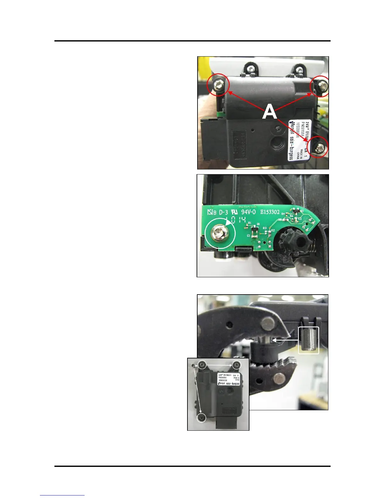
2. Detach the Motor Assembly. Remove the
three (3) screws [A] holding the Pinch
Valve Motor Assembly on the Pinch Valve
Body. Remove the Motor Assembly.
3. Remove the single screw, shown, and then
remove the Dual Pinch Valve Sensor PC
Board from the Valve body.
4. Install the new Dual Pinch Valve Sensor PC
Board using the screw removed in previous.
NOTE: Make sure the PC Board is installed
flush against the Pinch Valve body.
5. Install (3) metal Inserts in the Motor
Assembly mounting holes.
The Inserts are added to align the Motor
Assembly with the Valve Body during re-
assembly; thereby keeping the Pinch Valve
Shaft aligned. Since the Sensor Flag is
mounted to the Pinch Valve Shaft,
misalignment can cause contact between the
Flag and Sensors; causing damage to the
sensors.
With the rounded end of the insert
facing down, press the three (3) inserts
into the Motor Assembly mounting
holes as shown.
NOTE: Insert is self-aligning, but to
ensure it is evenly aligned with the
mounting hole and to prevent accidental
damage, use a flat surface (a flat metal
bar for example) to provide even pressure to press the insert in partially. Then use pliers or
another tool to press the insert the rest of the way in.

 Loading...

