SECTION 4
MEASUREMENTS & ADJUSTMENTS
50
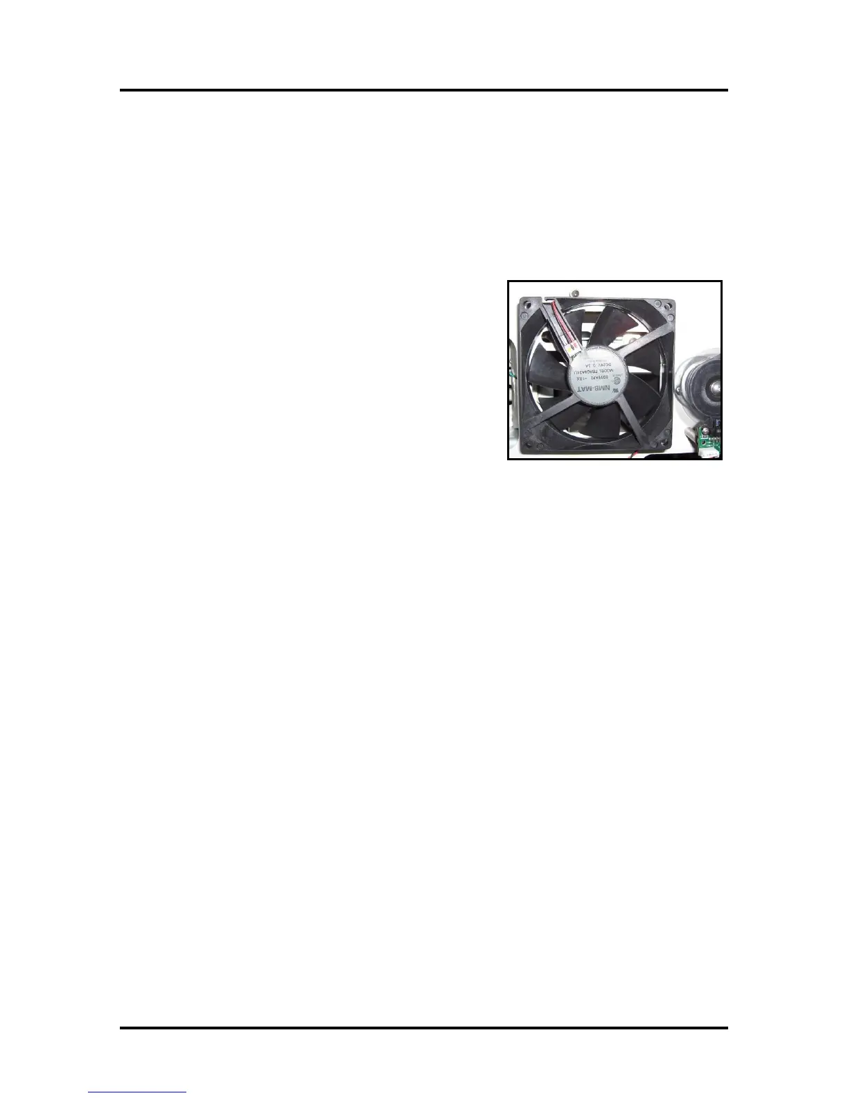
Dust Exhaust Fans
In conjunction with the Antistatic Brush Assembly the fans and air plenums are used to remove dust
and debris from media. This is done to reduce the amount of dust and debris that enters the print-
engine area. One fan is attached to the printer’s bottom frame and one is attached to the non-operator
side frame.
Measurement: Fans are turned on/off with the same signal/timing as the Feeder Motor drive signal.
Feeder Motor on = fans on. Feeder Motor off = fans off. You can use the Paper Feed test (press and
hold the PAPER button for 4 seconds) to activate.
Input (I/O Board, J2, MOTOR IN): see Feeder Motor
signal
Output (I/O Board J3, J5, J11, J12, J13, FAN #): 24 VDC
Cleaning: Dust can be cleaned from the fans using a vacuum
and soft brush. To avoid damage; disconnect the fans from
the Interface (I/O) Board before cleaning. A spinning fan will
generate voltage which could cause damage to the electronics.
Don’t forget to reconnect.
Troubleshooting Tip:
If the Feeder Motor is turning, but the fans are not turning on at the same time; check the fan
connections or replace the I/O board.
If the fans are receiving 24 VDC, but not turning, then check for obstructions and or replace the fan.
You can safely switch any of the FAN connection positions for the purpose of troubleshooting.
Feeder Motor (feed section)
The Feeder Motor, in the feed section, gets its drive from J4 on the Interface (I/O) Board. The I/O
board receives the motor power at J2. The motor power is provided by the DPCA board (from J18C).
Measurement:
You can use the Paper Feed test (press and hold the PAPER button for 4 seconds) to activate.
Input (I/O Board J2, MOTOR IN): Measure at I/O board from negative (right) side of D1 to
negative (right) side of D3.
Low Speed (6 ips, Best Print Quality): 5-7 VDC
High Speed (12 ips, Normal Print Quality): 10-12 VDC
Output (I/O Board J4, MOTOR OUT): Same as above.
J2 (input) is connected directly to J4 (output).
Troubleshooting Tips:
Fans are turned on/off with the same timing/signal as the feeder motor drive signal.
Feeder motor on = fans on. Feeder Motor off = fans off.
If the fans are turning ON, but the Feed Motor isn’t driving; check motor connection from the I/O
board (J4) to the motor. Also check for power at the motor. If you are getting power to motor, but no
motor drive, then you may need to replace the motor.
If the Feed Motor and fans are NOT turning on than there are many fault possibilities:
- A logic fault is keeping the system from driving the motor. Check Toolbox for error.
- A fault with the connection between the Main PC Board (P2006) and DPCA board .
- A problem with the DPCA board. Check output J18C on DPCA board.
- The connection from the DPCA board (J18C) to the I/O board (J2) is faulty.

 Loading...

