SECTION 5
DISASSEMBLY AND ASSEMBLY
101
Print Engine Basic Disassembly
The Print Engine must be removed from the Printer for these procedures. See "Removing the Print Engine"
in previous pages. It is also assumed that the ink tanks, printhead and service station are removed.
Removing the Print Engine Base
Provides access to parts located underneath the
Print Engine.
1. Remove Ink Waste Tray from below Ink
Reservoirs and put aside.
2. Remove Engine Base. Remove (6) T-10
screws, (3) on each side) of the Print Engine
Assembly. (Set aside for reassembly).
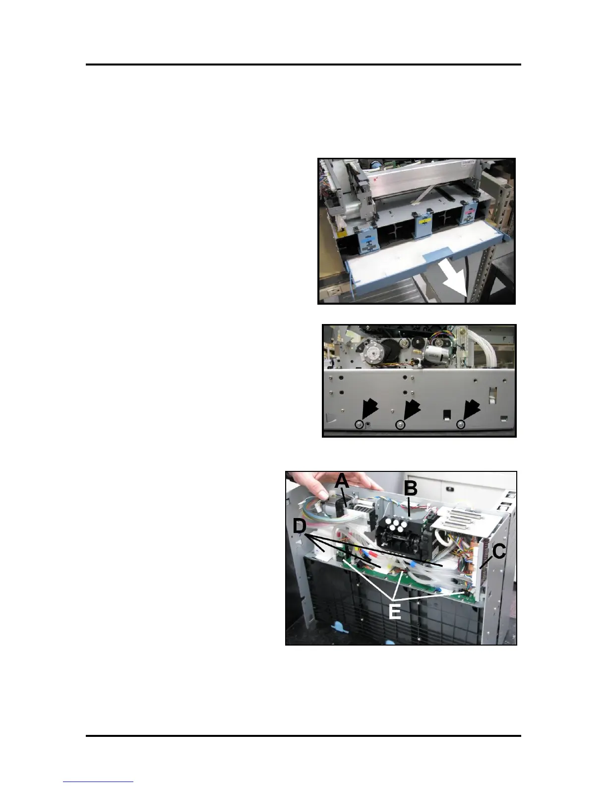
Print Engine Components -- Underside
[A] Peristaltic Pump
[B] Dual Pinch Valve
[C] DPCA Board
[D] Buffer Boxes (3 Sets of 2)
[E] Q/A Chip Assembly for Ink Tanks (3
– one per Buffer Box)

 Loading...

