SECTION 4
MEASUREMENTS & ADJUSTMENTS
57
Interface (I/O) Board Test Points
This board is located on the non-operator side of the printer.
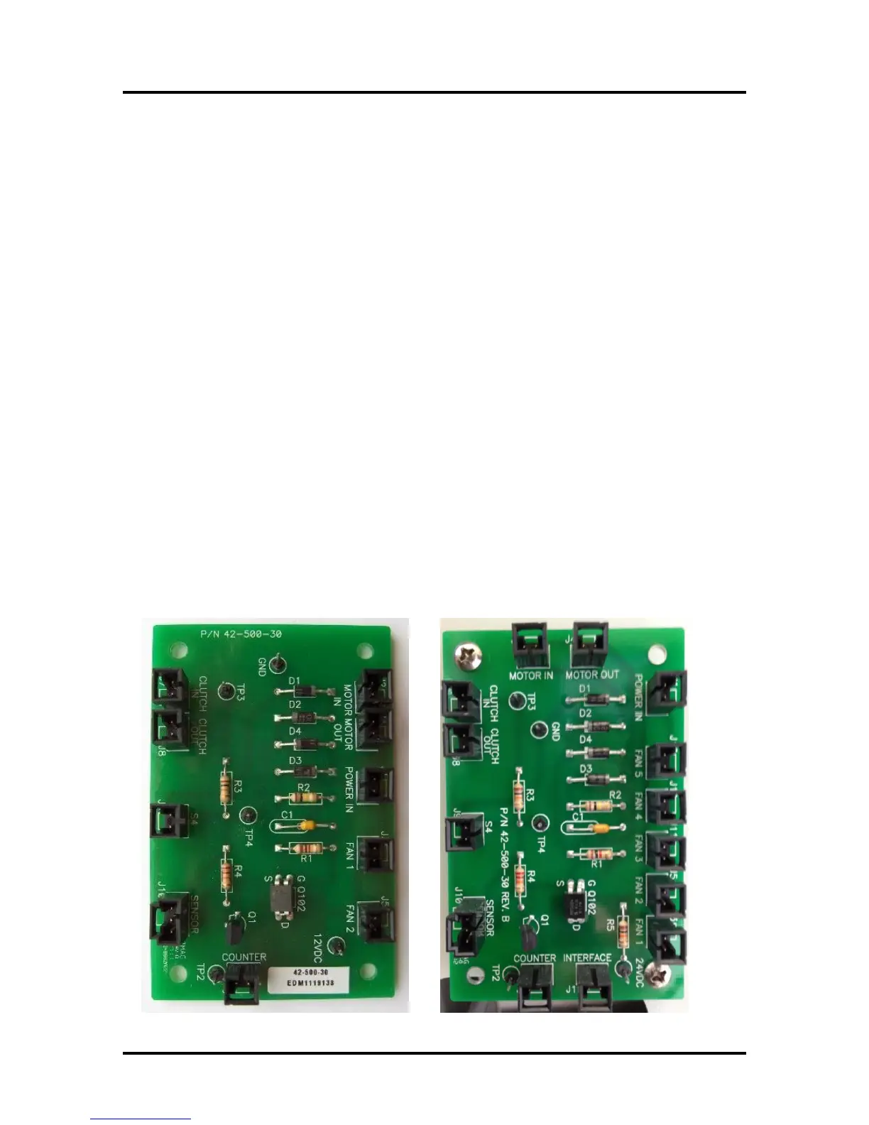
NOTES: There are two versions of the Interface (I/O) Board (42-500-30 and 42-500-30 Rev B).
The Rev B board has additional FAN connections.
The measurement information shown below is valid for both.
GND: Logic Ground
Connect your ground lead here for all measurements, except TP3 (clutch).
24VDC (12VDC): Power In
24 VDC. Improperly tagged on original version of board; should be 24VDC.
TP2: Counter
3 VDC open (no paper); 0 VDC interrupted (paper present)
Count should also increase, by one digit, each time the Feed Sensor is interrupted.
TP3: Clutch
Must measure from TP3 to the bottom pin on J8 (Clutch Out).
24 VDC = on (engaged), 0 VDC = off (disengaged)
TP4: Sensor (Feed Sensor)
0 VDC open (no paper); 7.5 VDC interrupted (paper present)
You can also use the counter to verify that the Feed Sensor is working.
Count will increase each time the Feed Sensor is interrupted.
Motor (In): Measure from right side of D1 to right side of D3
0 VDC = off (no Feeder Motor drive)
5-7 VDC = low speed (6 ips, Best Quality)
10-12 VDC = high speed (12 ips, Normal Quality)
Interface Board (42-500-30)
Interface Board (42-500-30 REV. B)

 Loading...

