SECTION 4
MEASUREMENTS & ADJUSTMENTS
51
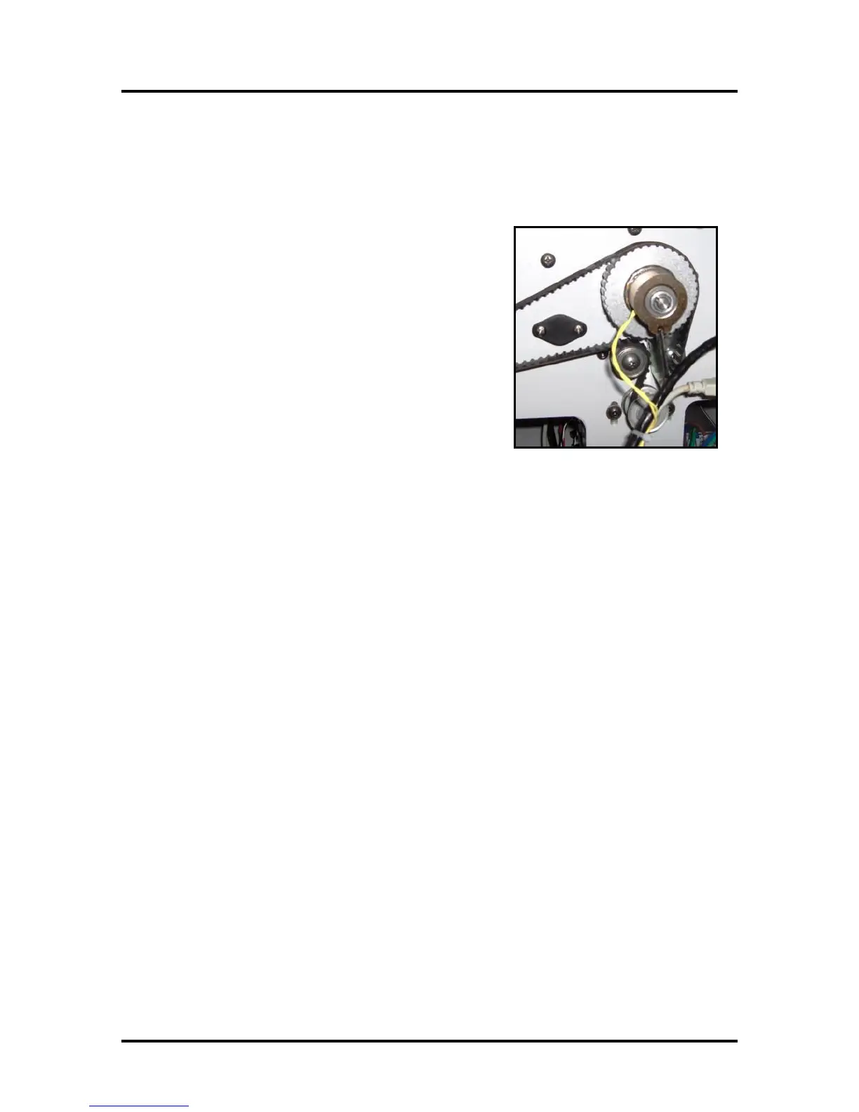
Clutch (Feed Roller Drive)
The clutch is used to engage/disengage drive to the feed rollers. When the Feeder Motor is driving and
the clutch is engaged; the feed rollers are driven to deliver media into the print engine.
Measurement:
To check the clutch for proper operation:
Measure from TP3, to the bottom pin on J7 (Clutch In), on
the Interface (I/O) Board, while performing a Paper Feed test
(press and hold the PAPER button for 4 seconds).
- You should measure 24 VDC when the clutch is engaged.
- You should measure 0 VDC when the clutch is disengaged.
Clutch Resistance Check:
Measure with the clutch disconnected from I/O Board.
- A good clutch will read ~225 Ohms
- A bad clutch or bad connection to the clutch will read open.
Troubleshooting Tips:
If you are NOT getting any drive to the Clutch, during
the Paper Feed Test; then the I/O Board (Clutch Out) may NOT be receiving a drive signal from
the Main PCB. In this case the issue may be as simple as the Paperpath Sensors being interrupted.
Toolbox will normally show PaperPath_PaperJam or PaperPath_PrintZone_Blocked. This issue
needs to be resolved before the system will engage the clutch.
If you are NOT getting any drive to the Clutch, during the Paper Feed Test and the Toolbox
displays “PaperPath_Feed_Timeout”.
Check that the Feed Sensor is working properly. A interrupted feed sensor or a sensor that
intermittently reads uninterrupted/interrupted can cause this issue.
If the Main PCB was recently removed/replaced; J551 may have been mistakenly attached to the
wrong point. Check the connection J551 on the Main PCB.
During the paper feed test; if the Dust Exhaust Fans are turning on but the Clutch and Feed Rollers
are not engaging; then you can temporarily connect one of the Fans to the “Clutch In” (J7)
connection on the I/O Board to verify that the I/O Board is providing a Clutch signal.
If the fan, temporarily connected to J7, drives during the Paper Feed Test then the clutch signal to
the I/O Board is OK. In this case the problem is most likely with the Clutch and or Feed Roller
Drive Pulley.
If the Fan, temporarily connected to J7, does not drive, then this indicates that the clutch signal is
not being received by the I/O Board. In this case, check connection J551 at the Main PCB and
check the cable (J8 from I/O Board to J551 on Main PCB) for possible damage.
Check the output at the J551 on the Main PCB. It should provide 24 VDC to drive the clutch and
0 VDC when not driving the clutch. If J551 on the Main PCB doesn’t provide 24VDC to drive the
clutch; try disabling the Feed Sensor by removing the reflector (plate that reflector attaches to)
from above the sensor. If the clutch (or fan connected to Clutch signal) drives with the reflector
removed; then the issue is most likely being causes by the feed sensor and or reflector.
NOTE: Don’t forget to return the Fan to its proper location on the I/O Board; after performing the
above tests.

 Loading...

