Appendix H – Factory Service................................. H-1
H.1 Service Form .................................................. H-2
List of Figures
Figure No. Page
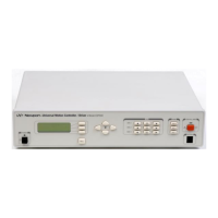
Figure 1.1: ESP 300 Controller/Driver ..........................................1-6
Figure 1.2: ESP300 Front Panel with displays ..............................1-9
Figure 1.3: Rear Panel of the ESP300..........................................1-10
Figure 2.1: Menu Section................................................................2-2
Figure 2.2: Menu Item.....................................................................2-3
Figure 2.3: Motion from the Front Panel Displayed ......................2-3
Figure 3.1: Command Syntax Diagram ..........................................3-7
Figure 4.1: A Contour with Multiple Circular Moves ....................4-5
Figure 4.2: A Contour with Multiple Linear and Circular Moves 4-5
Figure 4.3: Block Diagram of Via Point Data Handling
By Command Processor.............................................4-6
Figure 4.4: Block Diagram of Via Point Data Handling
By Trajectory Generator...........................................4-7
Figure 4.5: Block Diagram of Closed Loop Stepper Motor
Positioning .......................................................... 4-11
Figure 5.1: Typical Motion Control Systems ..................................5-1
Figure 5.2: Position Error Test.......................................................5-4
Figure 5.3a: High Accuracy for Small Motions..............................5-5
Figure 5.3b: Low Accuracy for Small Motions...............................5-5
Figure 5.4: Effect of Stiction and Elasticity on Small Motion ........5-6
Figure 5.5: Error Plot .....................................................................5-6
Figure 5.6: Error vs. Motion Step Size ...........................................5-7
Figure 5.7: Hysteresis Plot .............................................................5-8
Figure 5.8: Real vs. Ideal Position..................................................5-9
Figure 5.9: Pitch, Roll and Yaw Motion Axes.................................5-9
Figure 5.10: Pitch, Yaw and Roll Motion Axes...............................5-9
Figure 5.11: Wobble Generates a Circle ......................................5-10
Figure 5.12: Position, Velocity and Average Velocity................. 5-11
Figure 5.13: Servo Loop ...............................................................5-14
Figure 5.14: P Loop ......................................................................5-15
Figure 5.15: PI Loop.....................................................................5-15
Figure 5.16: PID Loop..................................................................5-16
Figure 5.17: Trapezoidal Velocity Profile ....................................5-17
Figure 5.18: PID Loop with Feed Forward..................................5-17
Figure 5.19: Tachometer-Driven PIDF Loop...............................5-18
Figure 5.20: Trapezoidal Motion Profile......................................5-19
Figure5.21: Position and Acceleration Profiles ...........................5-19
Figure 5.22: Home (Origin) Switch and Encoder Index Pulse.....5-21
Preface ix

 Loading...