Chapter 10
10-31
Appendices
● Inverter Outputs: Register Number 0009 Hex
Note Valid when “18" (communications output) is set for multiple-function outputs 1 to 3 (n057 to
n059). By performing this setting, the relevant output terminal can be turned ON and OFF
through communications.
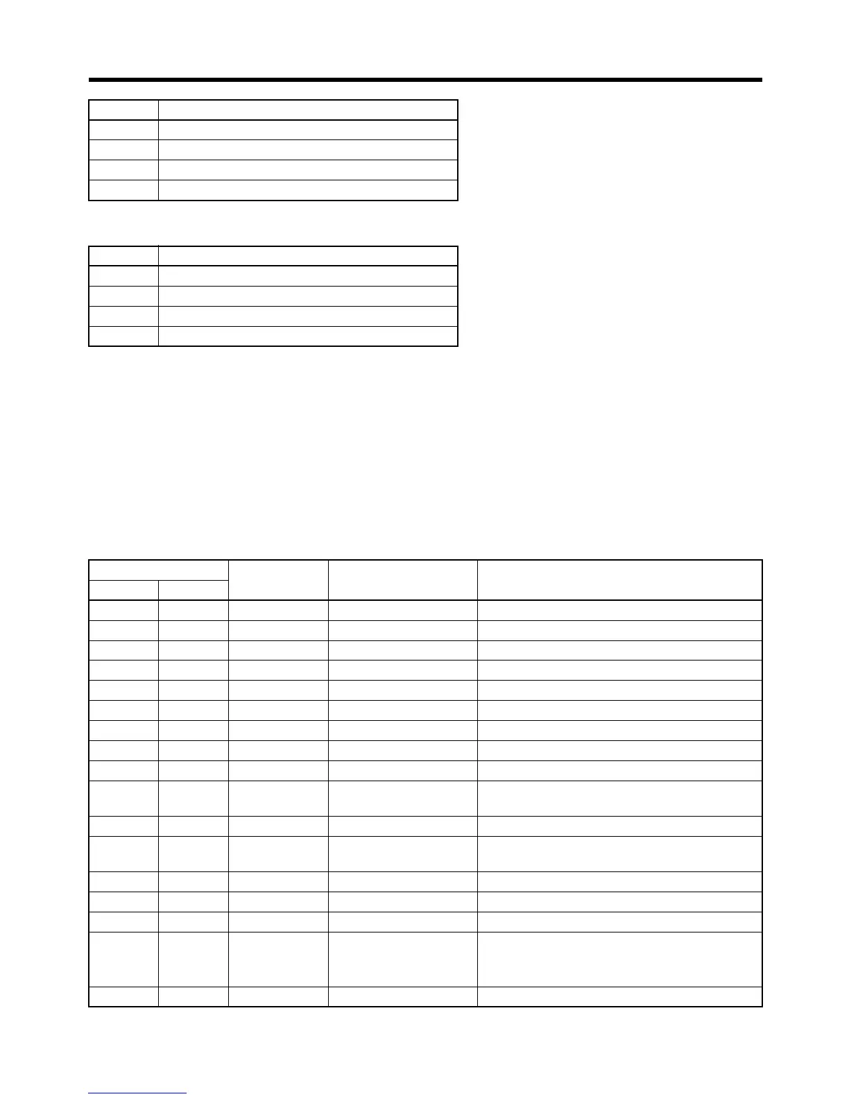
10-4-2 Inverter Monitoring Functions
All Inverter monitoring can be accessed. To read Inverter status, fault monitoring, alarm monitoring, I/
O status monitoring, error log, etc., specify the register number from the following table and read the
data.
7 Not used.
8 External fault input (1: EFO)
9 Fault reset (1: reset)
10 to 15 Not used.
Bit Content
0 Multi-function contact output (1: ON)
1 Multi-function output 1 (1: ON)
2 Multi-function output 2 (1: ON)
3 to 15 Not used.
Class 64 Register
number (hex)
Function Content
Instance Attribute
00 20 0020 Status signal Refer to the following Status Signals table.
00 21 0021 Fault status Refer to the following Fault Status table.
00 22 0022 Data link status Refer to the following Data Link Status table.
00 23 0023 Frequency reference Follows setting for n035.
00 24 0024 Output frequency Follows setting for n035.
00 --- 0025 to 0027 Not used. ---
00 28 0028 Output voltage Read with 1 (V) = 1 decimal
00 29 0029 Fault status 2 Refer to the following Fault Status 2 table
00 2A 002A Warning status Refer to the following Warning Status table
00 2B 002B Input terminal status Refer to the following Input Terminal Status
table.
00 2C 002C Inverter status Refer to the following Inverter Status table.
00 2D 002D Output terminal status Refer to the following Output Terminal Status
table.
00 2E 002E Inverter status 2 Refer to the following Inverter Status 2 table
00 --- 002F to 0030 Not used. ---
00 31 0031 Main circuit DC voltage Read with 1 (V) = 1 decimal
00 32 0032 Torque reference Read with 1 (%) = 1 decimal
Rated motor torque = 100%.
Read with +/
−.
00 --- 0033 to 0034 Not used. ---
Bit Content
 Loading...


