Chapter 10
10-84
Appendices
10-7 3G3FV Register Numbers, Classes, Instances, and
Attributes
10-7-1 Inputting Control/Frequency
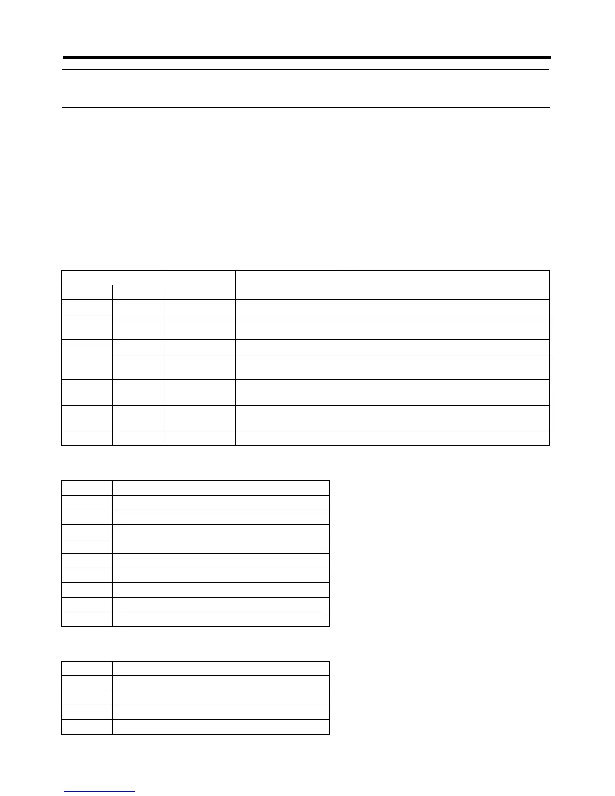
The Inverter's various control inputs are allocated to the registers shown in the following table. For
example, to set the frequency reference and begin operation, first set the reference value to the fre-
quency reference register “0001,” and then write the run command to the Inverter's run command
register “0000."
Note 1. Set values are retained until changed by the next writing operation.
Note 2. The following registers are in RAM, so they are all cleared to zero when the Inverter's power
supply is turned OFF.
● Inverter Run Commands: Register Number 0000 Hex
● Inverter Outputs: Register Number 0009 Hex
Class 64 Register
number (hex)
Function Content
Instance Attribute
00 00 0000 Inverter run command (Refer to table below.)
00 01 0001 Frequency reference Sets frequency reference value. (See note
1.)
--- --- 0002 to 0006 Not used. ---
00 07 0007 Multi-function analog
output 1 (See note 2.)
+11 V = 02D6 hex
00 08 0008 Multi-function analog
output 2 (See note 2.)
+11 V = 02D6 hex
00 09 0009 Inverter output (See
note 3.)
(Refer to table below.)
--- --- 000A to 000F Not used. ---
Bit Content
0 Forward/stop (1: Forward operation)
1 Reverse/stop (1: Reverse operation)
2 Multi-function input 1
3 Multi-function input 2
4 Multi-function input 3
5 Multi-function input 4
6 Multi-function input 5
7 Multi-function input 6
8 to 15 Not used.
Bit Content
0 Multi-function contact output (1: ON)
1 Multi-function output 1 (1: ON)
2 Multi-function output 2 (1: ON)
3 to 15 Not used.