Chapter 3
3-28
Setup and Wiring
● 3G3RV-PDRT2 DeviceNet Communications Card
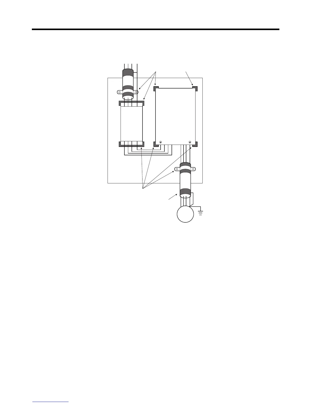
Mount the DeviceNet Communications Card as shown in the diagram. Detailed precautions are given
below.
• Remove any coating on the footprints of EMC filter, Inverter, and metal mounting plate in order to
ensure a metal contact between grounding faces.
• Attach Option Units to the Inverter.
• Use a shielded cable for the Inverter's power supply line and connect via the EMC-compliant input
noise filter with the shortest cable length possible. Ground the shield at both ends of the cable.
• Use the shortest ground wire possible. For 400-V Inverters, ground the neutral point on the power
supply.
• Use a shielded cable for the cable between the Inverter and motor as well. Keep the cable as short
as possible (20 m max.) and ground the shield at both ends of the cable. It is effective to mount a
clamp filter right next to the Inverter's output terminals.
• Use a conductive cable clamp to directly ground the shield to the ground plate.
• Directly ground the motor frame.
• Use a ZCAT3035-1330 Clamp Filter on the communications cable, wind the cable in a loop around
it, and keep it away from the control panel.
• Use reinforced insulation or double insulation for the DC power supply for communications.
RS
Mains
Load
Metal Plate
Filter
Inverter
IM
TPE
RST UVW
Remove any coating on
the grounding faces.
Wiring length:
40 cm max.
Remove any coating on
the grounding faces.
Wiring length:
20 m max.



 To Next Page