4 Setting the Controller
4 - 54
Vision System FH/FHV/FZ5 Series User’s Manual (Z365)
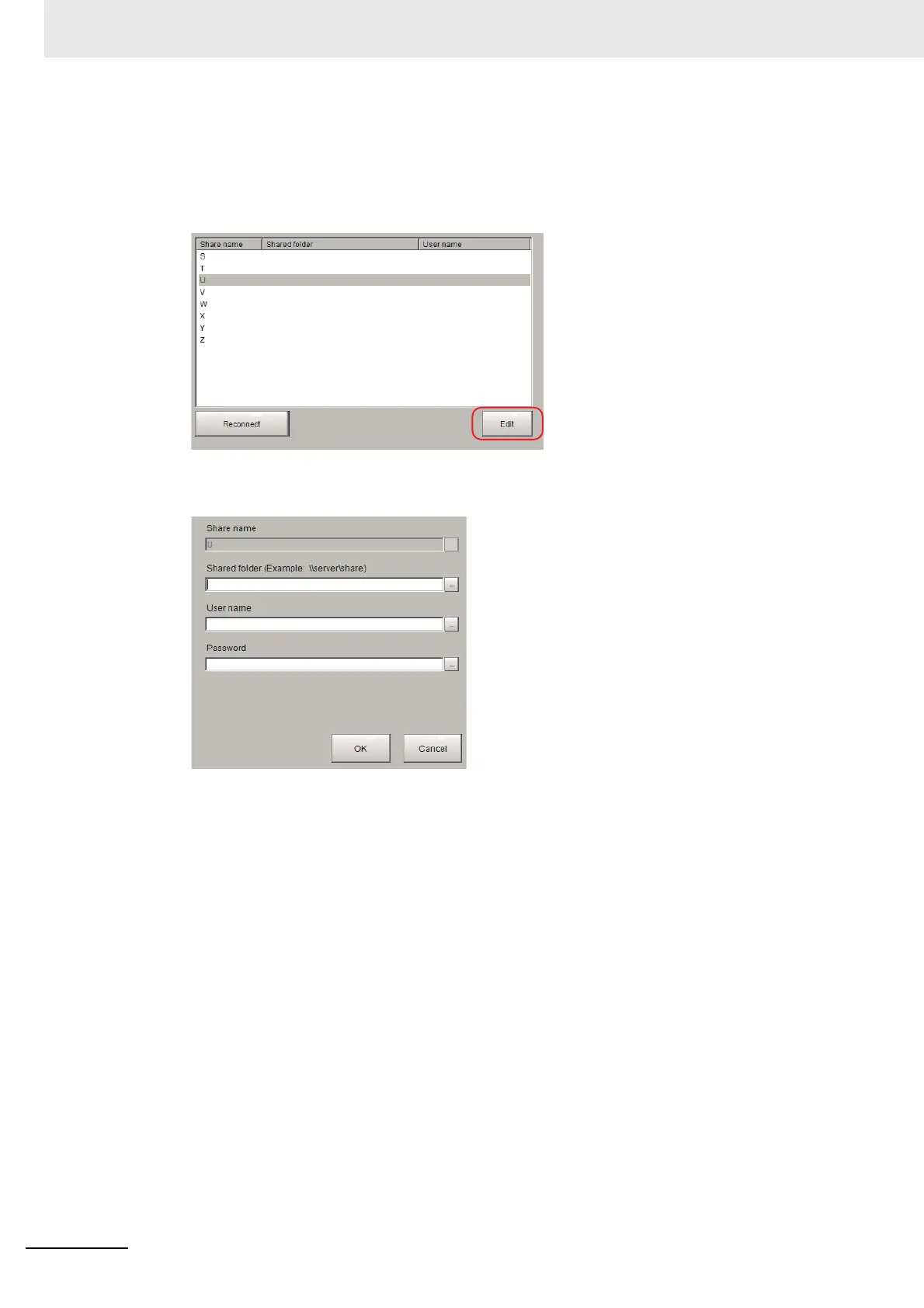
About [Edit]
You can edit Network drive’s name e.t.c.
Setting Procedure of [Edit] is the following.
1 Select Network drive that you want to edit.
2 Click [Edit].
3 Enter Share name, Shared folder, User name and Password.
 Loading...


