8 Setting Windows
8 - 14
Vision System FH/FHV/FZ5 Series User’s Manual (Z365)
8-3 Arranging Windows
[Layout Functions]
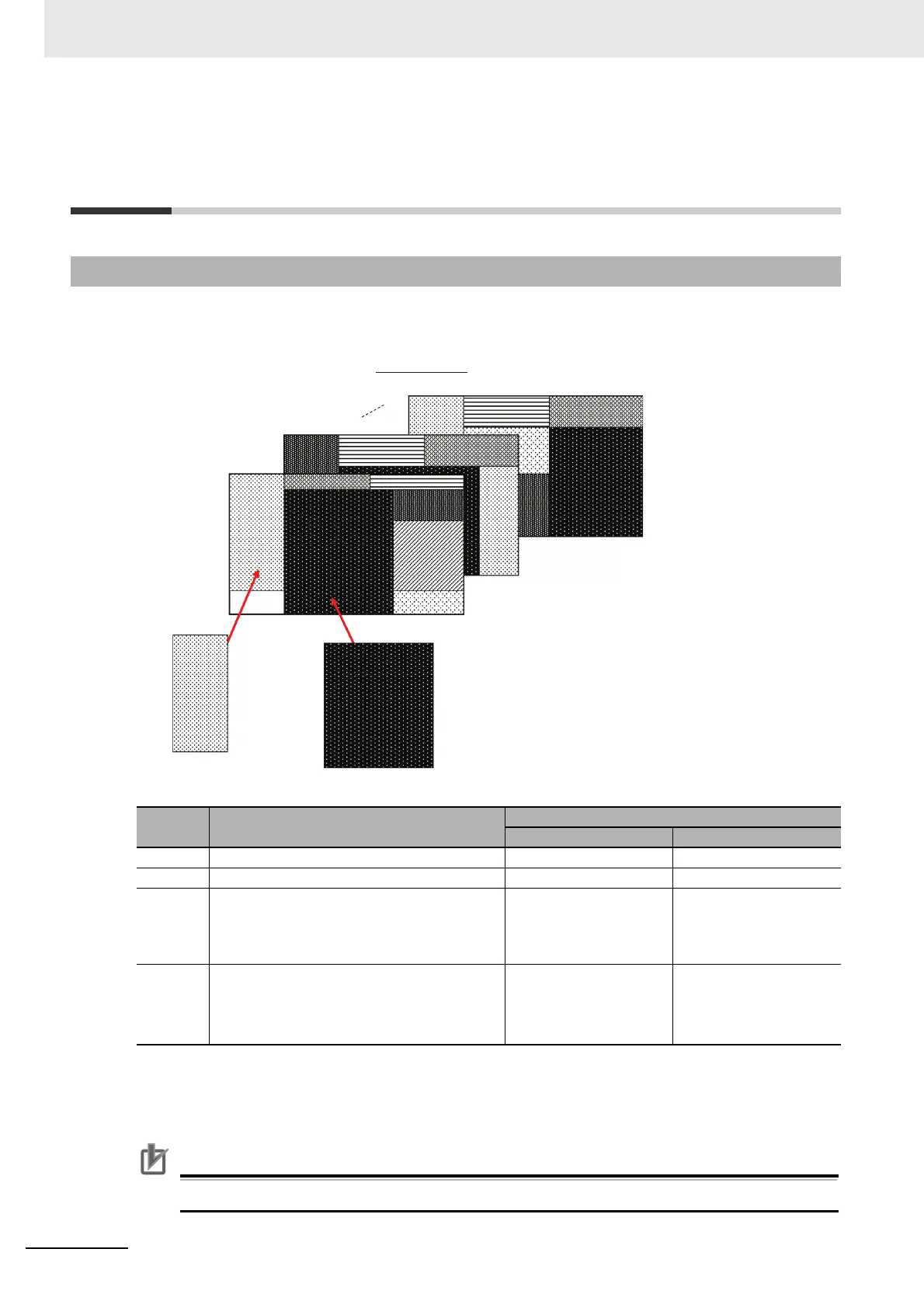
Configuration elements for the Main Windows (called window parts) can be laid out and displayed anywhere.
You can create a maximum of 9 Main Windows from layout 0 to layout 8.
Each Layout Window is set as follows by default:
• You can use these layouts to create Main Windows that show only the information that the operator
needs, such as a window that shows only the image and the OK or NG status for operation in the field.
• You can change the position and size of the image display, or the processing unit to be displayed for
each product type, inspection, or measurement.
If the operation mode is set to Multi-line Random-trigger Mode, create a layout for each line.
8-3-1 Arranging Window Elements (Layout Modification)
Layout Default setting
Behavior of output signals
RUN signal output Signal output of results
Layout 0 Layout 0 is set as an adjustment window. OFF OFF
Layout 1 Layout 1 is set as a run window. ON ON
Layouts 2
to 7
Layouts 2 to 7 are for user-defined purposes
and are created as they are needed. By
default, these layouts have the same settings
as layout 0.
OFF OFF
Layout 8 Layout 8 is set as a remote operation window.
When an error occurs in Layout 8, error dialog
appears as a text string in the Error Pane
instead of in an error dialog box.
OFF OFF
Flow Display Pane
Image Pane or other pane
Main Windows
Window parts can be placed anywhere.
Layout 0
Layout 1
Layout 8
 Loading...


