1 Overview
1 - 2
Vision System FH/FHV/FZ5 Series User’s Manual (Z365)
1-1 Checking the System Configuration
The FH/FHV/FZ5 is a Vision Sensor that uses a controller to process measurements of objects that are
imaged with a Camera.
You connect an LCD for operations and monitoring, and various Cameras to the FH/FHV/FZ5-series
Sensor Controller.
You connect external devices, such as a PLC or a computer, through a parallel, Ethernet, or RS-232C
cable.
You can connect up to eight Cameras, depending on the model of the Controller.
To measure more than one line with a single Sensor Controller, you assign the Camera for the mea-
surements to each line beforehand, and switch between Cameras during the measurement flow.
For details of the system configuration each series or basic configuration, refer to the Vision System
FH/FHV/FZ5 series Hardware Setup Manual (Cat. No. Z366)/FHV Series Smart Camera Setup Manual
(Z408).
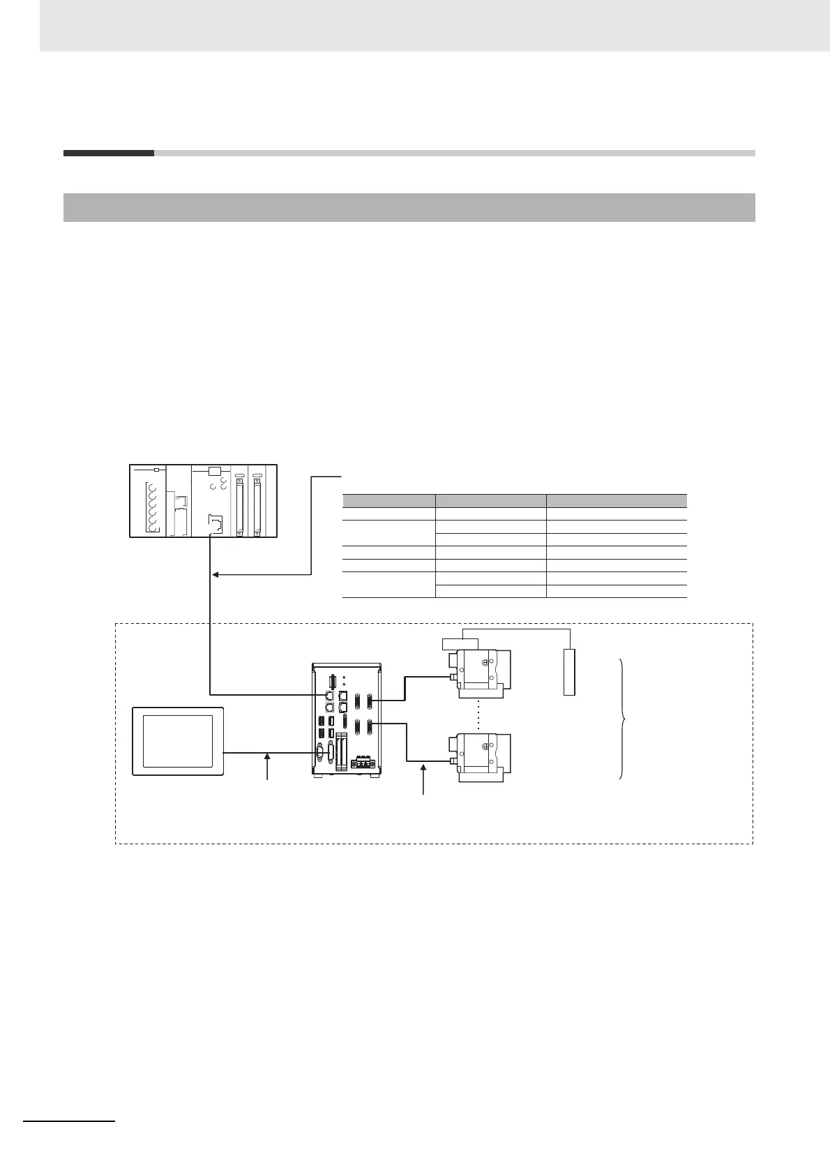
1-1-1 System Configuration
Communications protocol
Communications cable Connector on the FH
Parallel Parallel I/O cable I/O connector
Ethernet cable Ethernet connector PLC Link
RS-232C cable RS-232C connector
EtherNet/IP Ethernet cable Ethernet connector
EtherCAT Ethernet cable
Connector for EtherCAT communications
Ethernet cable Ethernet connector Non-procedure
RS-232C cable RS-232C connector
LCD
FZ-M08
(8.4-inch)
Camera
Camera
Sensor Controller
• Controller with 2 Camera channels
• Controller with 4 Camera channels
• Controller with 8 Camera channels
Camera Cable (e.g., FZ-VS3)
Communications cable
External device (e.g., PLC)
*1. FZ-MEM2G or FZ-MEM8G USB Memory is sold separately.
Lighting
Monitor cable
(e.g., FH-VMDA)
Up to 2, 4, or 8 Cameras
depending on the model of
the FH/FZ5-series Sensor
Controller
Example
FH series System

 Loading...

