10 Advanced Usage
10 - 60
Vision System FH/FHV/FZ5 Series User’s Manual (Z365)
This section will use two Cameras to describe the procedures for setting the alignment flow and execut-
ing alignment.
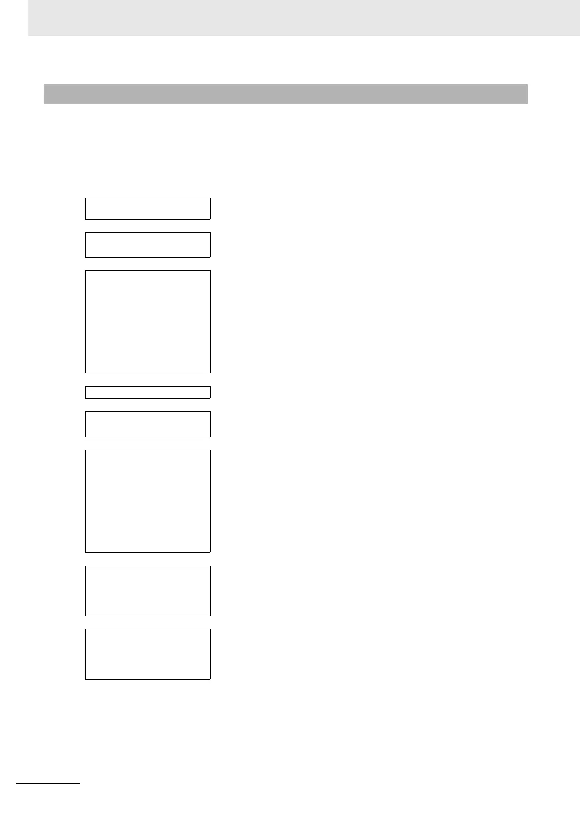
Example 1: Alignment Flow Example (Position Data Calculation and
Axis Movement Conversion) for Two Cameras
10-9-4 Alignment
Camera Image Input process-
ing item
· · · Select Camera 0.
↓
Calibration Data Reference
processing item
· · · Select the Vision Master Calibration or PLC Master Calibration processing
item on the calibration scene with the Calibration Data Reference.
↓
Position measurement pro-
cessing item
· · · Measure the position of the alignment marks or the position of a special
feature of the workpiece from the image in Camera 0.
To output the actual coordinates of the position, set [Calibration] on the
[Output parameter] tab page to OFF.
Out of the general measurement processing items (Inspections and Mea-
surements), you can use processing items with measurement results that
have an X and Y in the calculation strings.
Set the workpiece in reference position and then set the reference position.
↓
Camera Switching item · · · Select Camera 1.
↓
Calibration Data Reference
processing item
· · · Select Image Master Calibration or PLC Master Calibration on the calibra-
tion scene with the Calibration Data Reference.
↓
Position measurement pro-
cessing item
· · · Measure the position of the alignment marks or the position of a special
feature of the workpiece from the image in Camera 1.
To output the actual coordinates of the position, set [Calibration] on the
[Output parameter] tab page to OFF.
Out of the general measurement items (Inspections and Measurements),
you can use items with measurement results that an X and Y in the calcu-
lation strings.
Set the workpiece in reference position and then set the reference position.
↓
Transfer Position Data pro-
cessing item
· · · Use the two measurement positions to calculate the reference position and
reference angle of the workpiece.
Set [Reference XY] in the expression of the two-position measurement
processing item as position XY for point 0 and point 1.
↓
Position Data Calculation pro-
cessing item
· · · Calculate the measurement position and measurement angle of the work-
piece with the two-point measurement position.
Set [Coordinates XY] in the expression of the two-position measurement
processing item as position XY for point 0 and point 1.
↓

 Loading...

