10 - 61
10 Advanced Usage
Vision System FH/FHV/FZ5 Series User’s Manual (Z365)
10-9 Positioning workpieces for stage and
robot applications [Alignment Function]
10
10-9-4 Alignment
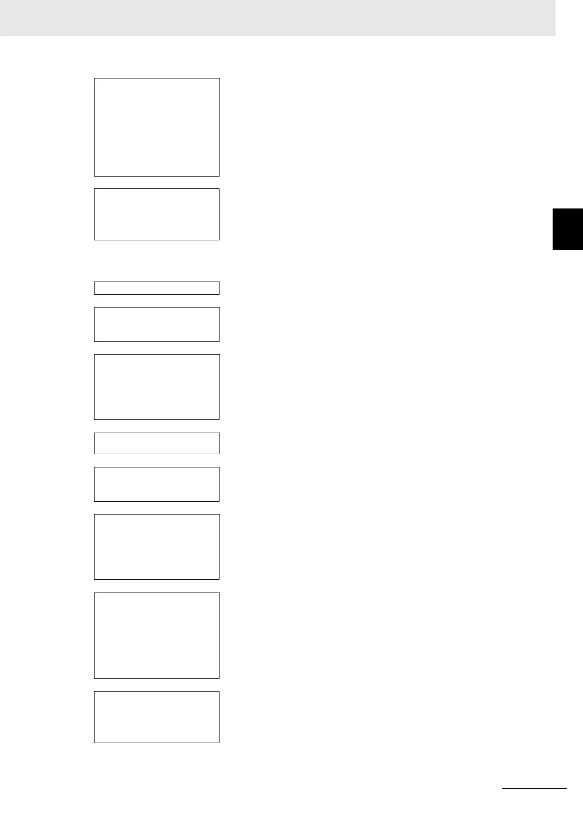
Example 2: Alignment Flow Example (Calc Axis Move by Multipoint) for Two Cameras
Convert Axis Movement pro-
cessing item
· · · Set the machine setting processing item to reference. Then set the expres-
sions for the two Position Data Calculation processing items, [Calculate
position XY] and [Calculate angle TH], in the [Reference position XY] and
[Reference angle], and the [Measurement position XY] and [Measurement
angle] in the Calc Axis Move processing item.
Before you execute the measurement, set the [Current setting] with the
position of the axis of the external device when the measurement was per-
formed.
↓
Data output processing item · · · Depending on the communications method, register either [Data output] or
[Fieldbus data output].
Send each [Axis movement] expression in the Calc Axis Move processing
item to the PLC.
Camera Image Input item · · · Select Camera 0.
↓
Calibration Data Reference
processing item
· · · Select the Vision Master Calibration or PLC Master Calibration processing
item on the calibration scene with the Calibration Data Reference.
↓
Position measurement pro-
cessing item
· · · Measure the position of the alignment marks or the position of a special
feature of the workpiece from the image in Camera 0.
To output the actual coordinates of the position, set [Calibration] on the
[Output parameter] tab page to OFF.
Set the workpiece in reference position and then set the reference position.
↓
Camera Switching process-
ing item
· · · Select Camera 1.
↓
Calibration Data Reference
processing item
· · · Select the Vision Master Calibration or PLC Master Calibration processing
item on the calibration scene with the Calibration Data Reference.
↓
Position measurement pro-
cessing item
· · · Measure the position of the alignment marks or the position of a special
feature of the workpiece from the image in Camera 1.
To output the actual coordinates of the position, set [Calibration] on the
[Output parameter] tab page to OFF.
Set the workpiece in reference position and then set the reference position.
↓
Calc Axis Move by Multipoint
processing item
· · · Set the machine setting processing item to reference. Then set the expres-
sions for the position measurement processing items, [Reference XY] and
[Measure XY] in the [Reference position XY] and [Measurement position
XY] in the Calc Axis Move by Multipoint processing item.
Before you execute the measurement, set the [Current setting] with the
position of the axis of the external device when the measurement was per-
formed.
↓
Data output processing item · · · Depending on the communications method, register either [Serial data out-
put] or [Fieldbus data output].
Send each [Axis movement] expression in the Calc Axis Move by Multi-
point processing item to the PLC.

 Loading...

