3 - 3
3 Basic Operations
Vision System FH/FHV/FZ5 Series User’s Manual (Z365)
3-1 Preparing the Controller and Cameras
3
3-1-1 Camera Setup
FH series Sensor Controllers support the CameraLink standard’s Base Configuration and Medium Con-
figuration.
The Medium Configuration enables use at a higher frame rate than the Base Configuration, reducing
image input time. The configuration that can be connected will depend on the connected cameras.
See the instruction sheet of the cameras you are using.
To connect a camera in the Medium Configuration, you will need to use two camera cables of the same
type and length to connect the camera and Sensor Controller (two-cable connection).
Sensor Controller camera connectors should be connected as a pair with ascending consecutive even
and odd numbered connectors.
The table below shows the camera connector and camera number assignments when connecting the
Sensor Controller and camera cable with a two-cable connection.
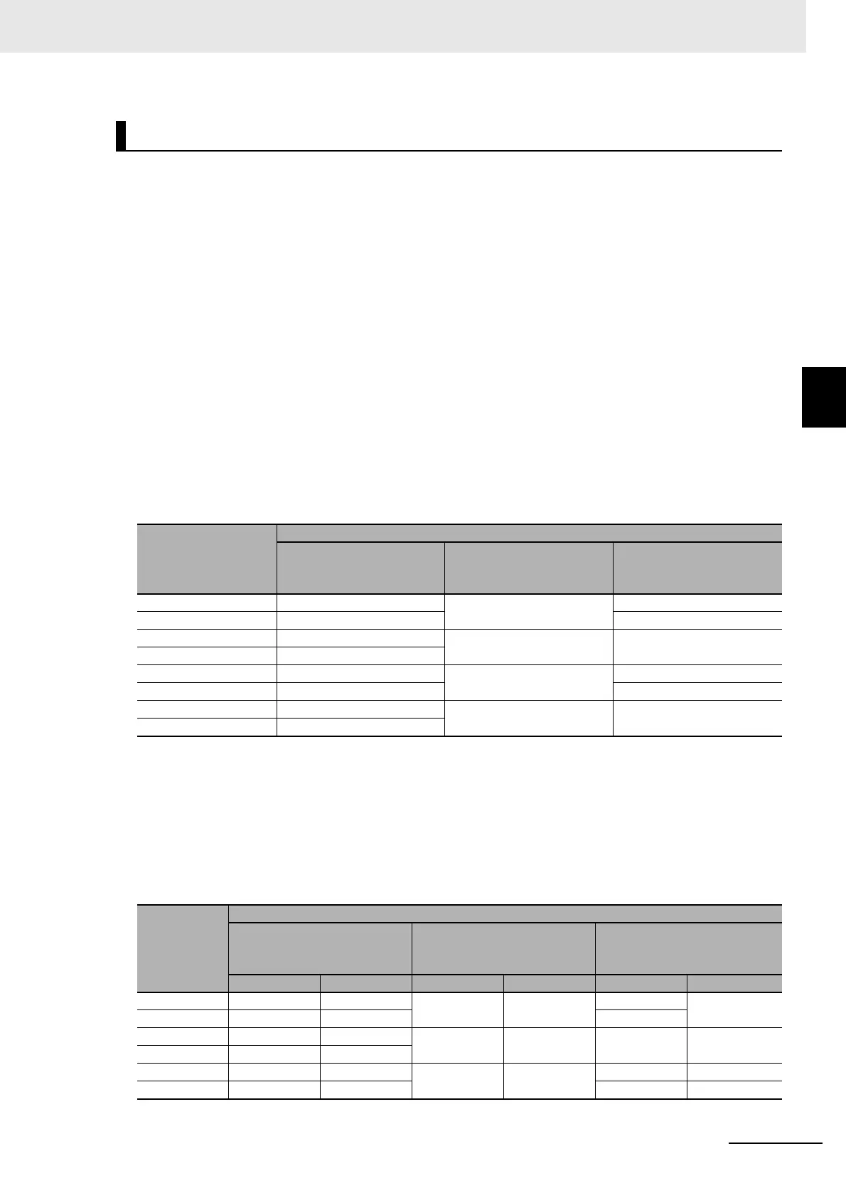
Camera numbers for operation modes other than multi-line random trigger
mode
The table below shows the camera connector and camera number assignments when the operation
mode is a mode other than the multi-line random trigger mode.
A number corresponding to a Sensor Controller camera connector number is assigned for the cam-
era number. When using two-cable connection, the even number in the pair of ascending consecu-
tive camera connector numbers is assigned as the camera number.
Camera numbers for multiple-line random trigger mode
The table below shows the camera connector and camera number assignments when the operation
mode is the multi-line random trigger mode. This table is an example showing the camera number
assignments when the number of lines is two.
Camera numbers are assigned for each line in ascending order starting from 0. For two-cable con-
nection, camera numbers are assigned in ascending order regardless of camera connector number
pairs.
Using Two Cables for High-frame-rate Camera Use (FH series only)
Sensor Controller
camera connector
number
Camera number in application software
Example when all cam-
eras use one-cable con-
nection
Example when all cam-
eras use two-cable con-
nection
Example when combining
one- and two-cable con-
nection
0000
11 1
2222
33
4 4 4 Not connected
55 5
6666
77
Sensor Con-
troller cam-
era
connector
number
Camera number in application software
Example when all cameras
use one-cable connection
Example when all cameras
use two-cable connection
Example when combining
one- and two-cable connec-
tion
Line 0 Line 1 Line 0 Line 1 Line 0 Line 1
00 ---0
---
0
---
11 --- 1
22 ---2
---
2
---
33 ---
4 --- 0
---
0 --- Not connected
5 --- 1 --- 0

 Loading...

