1003
Serial Communications Instructions Section 3-24
Communications Settings
The communications settings of the Code Reader as given in the following
table. These are the default settings.
Set the PLC communications settings to the same values in the PLC Setup.
Only the end code needs to be set.
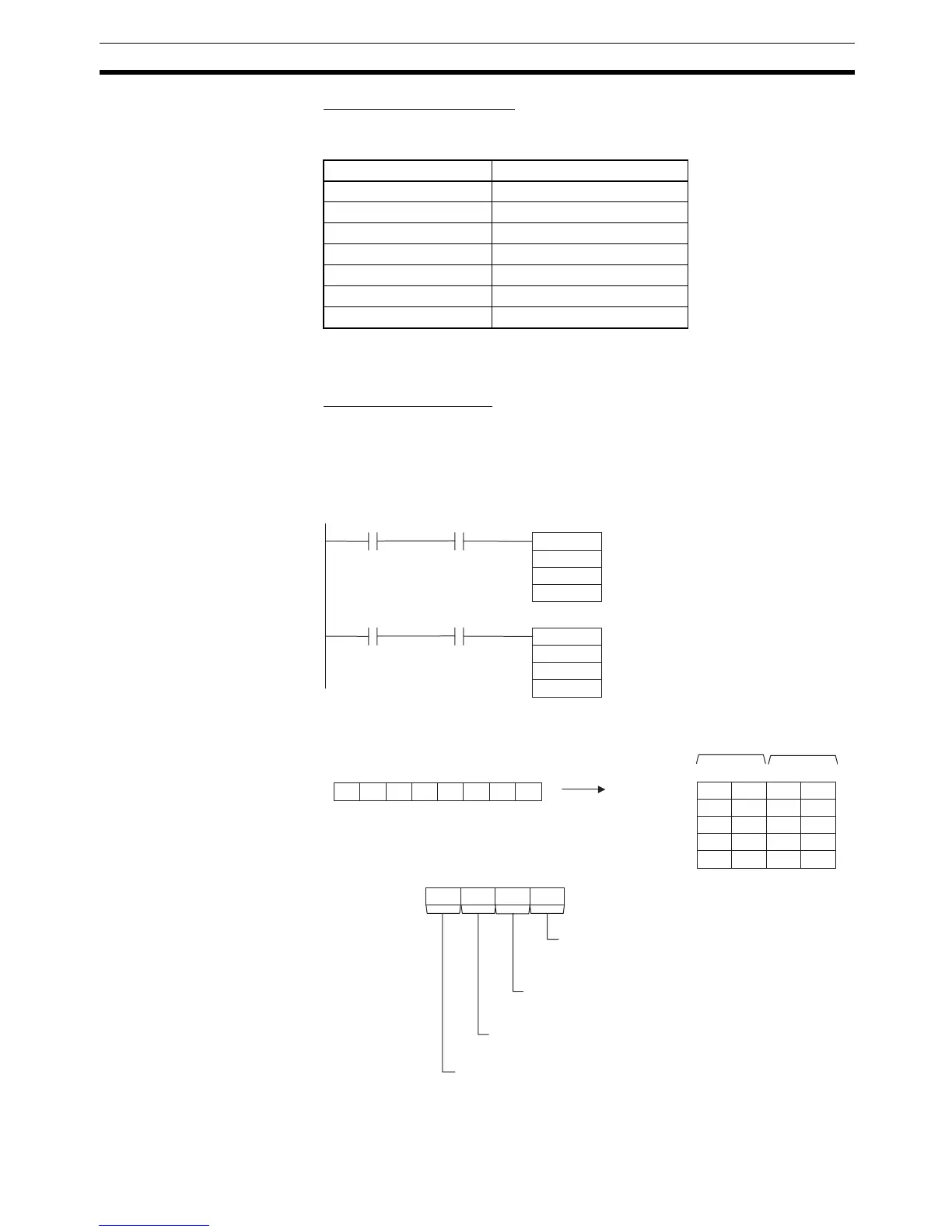
Programming Example
If CIO 000002 turns ON while the RS-232C Port Send Ready Flag (A39205)
is ON, the number of bytes of reading results specified in the RS-232C Port
Reception Counter (A393) are read from the Code Reader connected to the
CPU Unit’s built-in RS-232C port and stored starting from the upper byte of
D00100.
Item Setting
Communications mode No-protocol
Baud rate 38,400 bps
Data bit length 8 bits
Parity None
Stop bits 1
Start code None
End code #000D (CR)
2 F 03
3 0 63
15 8 71112 340
S: D00100
TXD
D00010
D00020
00001 A39205
S
C
&3
N
D00101
RXD
D00100
D00020
00002 A39206
A393
0 0 00
15 8 71112 340
C: D00020
31 2031
D00102
4F 4D 4F52
D00103
37 37 3637
D00104
=”06/08/11
Received
30 36 2F 30 38 2F 31 31
RS-232C Port Send
Ready Flag
RS-232C Port Receive
Ready Flag
RS-232C Port
Reception Counter
Always #0.
Serial Port Specifier
#0: CPU Unit's built-in RS-232C port
RS and ER Signal Control
#0:
No RS and ER signal control.
Byte Order
#0:
Most significant bytes first
Lower byte
Upper byte