1011
Serial Communications Instructions Section 3-24
Related Flags in the CPU Bus Unit Area
(n = CIO 1500 + 25
× unit number)
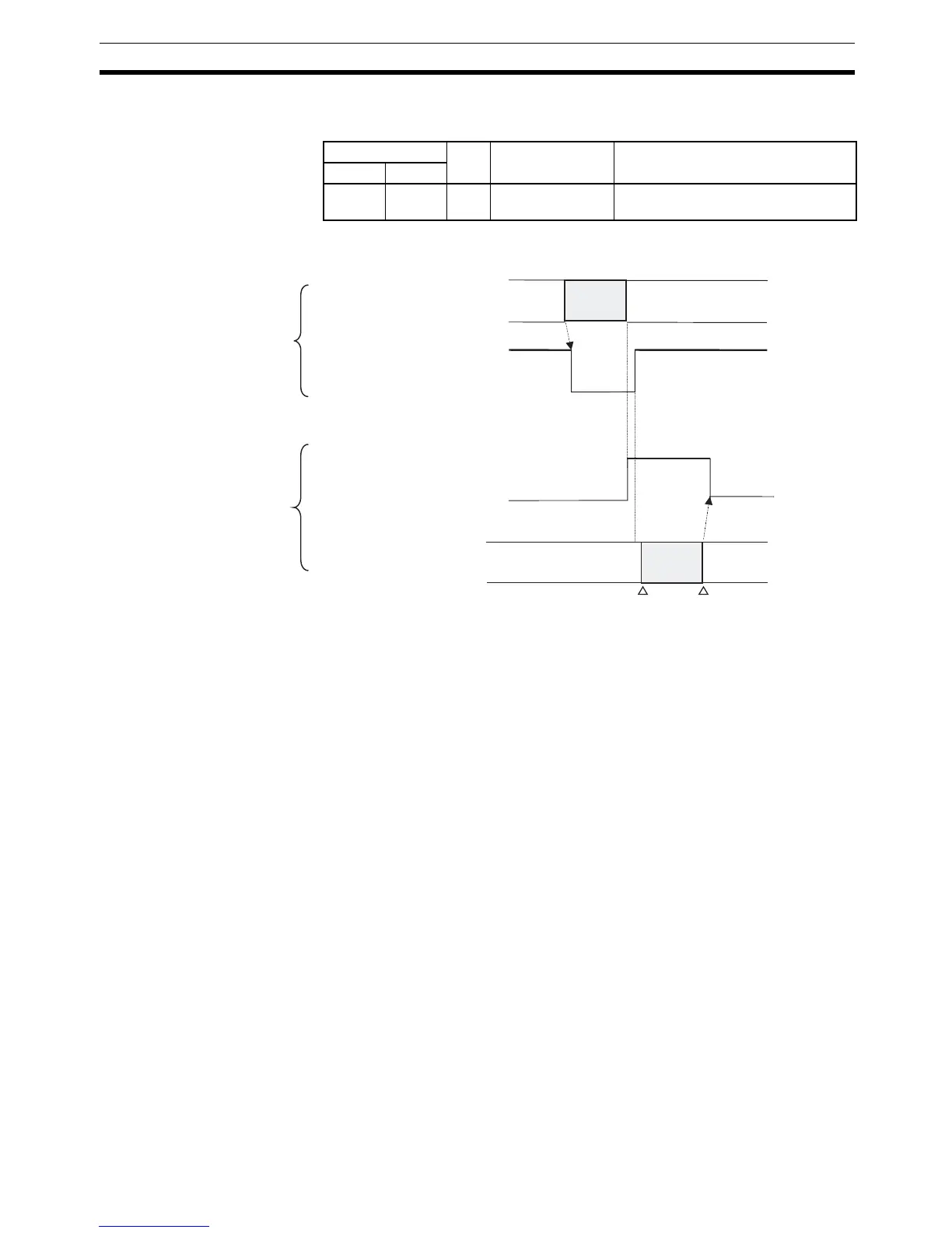
Example: Flag Operation The following diagram shows the operation of the Communications Port
Enabled Flag and TXDU Instruction Executing Flag.
Example: Sending Data When CIO 000000 is ON, A20203 (the Communications Port Enabled Flag) is
ON, and CIO 155905 (the TXDU Instruction Executing Flag for port 1) is OFF
in the following example, TXDU(256) outputs data through serial port 1 of the
Serial Communications Unit with unit number 2. The 5 bytes of output data
are read from the DM Area beginning at the rightmost byte of D00100 and
output through logical port 3 to a general-purpose device such as a printer.
Word Bit Name Status
Port 1 Port 2
n+9 n+19 05 TXDU Instruction
Executing Flag
0: TXDU(256) is not being executed.
1: TXDU(256) is being executed.
Instruction
execution
ON
OFF
Communications Port Enabled Flag
(A20200 to A20207 correspond to
communications ports 0 to 7.)
TXDU(256)
CPU Unit
TXDU Executing Flag
(Bit 5 of n+9 or n+19,
n = CIO 1500 + 25 x unit number)
ON
OFF
Send processing
Send
processing
Serial
Communications
Unit
Send starts.
Send completed.
 Loading...


