1012
Serial Communications Instructions Section 3-24
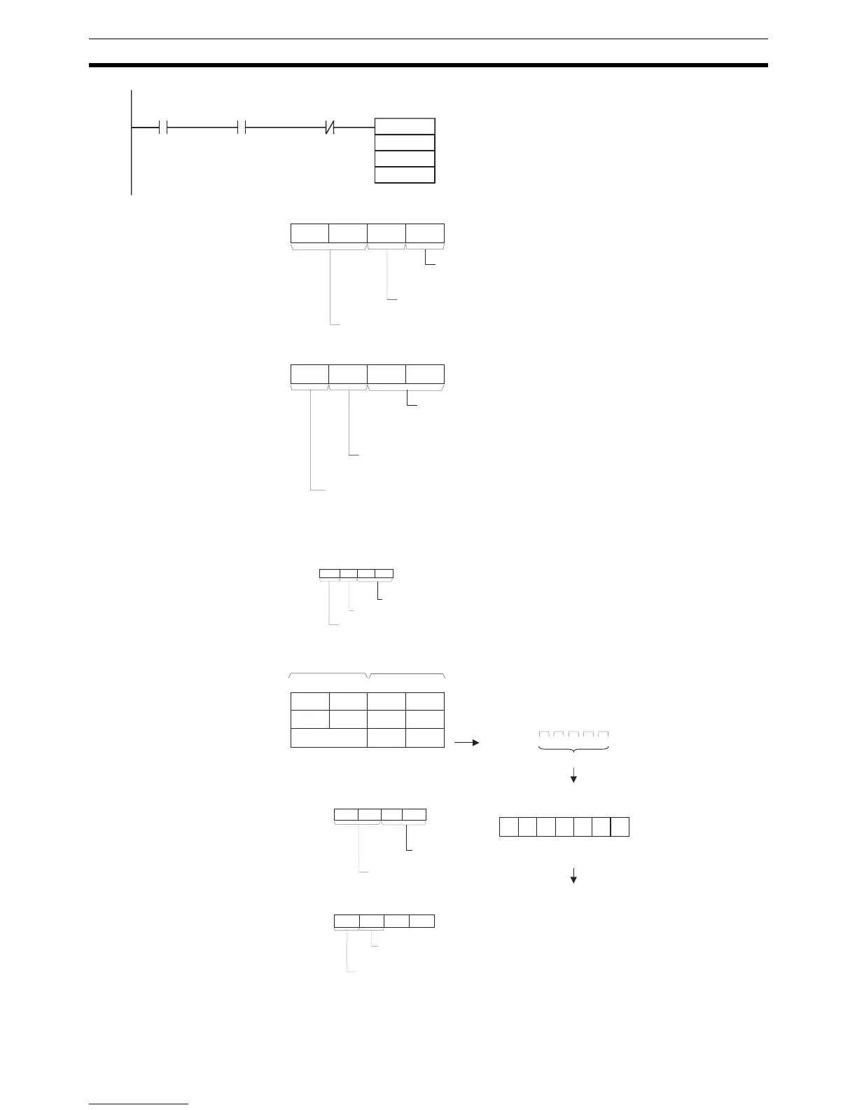
C+0: D00200
0
0 7 815
0
11 12
3
0
7 815
1
11 12
0 1
4 3
1 2
4 3
S:D00100
0 7 815
4 1 23
D00101
D A BC
D00102
E F
1 2 3 4 A B C D E F
3412ST AB CD EF ED
C+1:
3
0 7 815
0
11 12
8 8
4 3
D30204
0
7 815
2
11 12
0 3
4 3
0
D30205:
0 7 815
1
11 12
4 3
1
Always 00
RS and ER signal control
0: No RS and ER signal control
Byte order
1: Least significant bytes first
Communications Port
Enabled Flag
TXDU Instruction
Executing Flag
C+1: D00201
Serial Communications Unit's unit address (Unit
address as CPU Bus Unit)
12 hex = Unit number + 10 hex
Serial port number
1: Port 1
Note:
The serial port's unit address can be specified directly by setting the serial port number to 0 and
setting the Serial Communications Unit's unit address to the serial port's unit address.
(Set the unit address to 80 hex + 4 x unit number for port 1 or 81 hex + 4 x unit number for port 2.)
Port number specifier
3: Logical port 3
Serial Communications Unit's unit address
88 hex = 80 hex + 4 x unit number
Serial port number
0: Specify port directly.
Port number specifier
3: Logical port 3
Data sent.
In this example, a start and end code have been
specified in the allocated DM Setup Area.
ST: Start code (e.g., 02 hex)
ED: End code (e.g., 03 hex)
Most signifi-
cant bytes
Least signif-
icant bytes
Transfer order
5 bytes
Example allocated DM Setup Area settings:
Start code
(02 hex)
End code
(03 hex)
Start code and end code values
Start code and end code specifiers
End code specifier
(1: Use end code.)
Start code specifier
(1: Use start code.)
TXDU
D00100
D00200
&5
155905
A20203
S
C
N
000000