290
Timer and Counter Instructions Section 3-6
The loop in the program above has 4 input parameters which are used to start
all 100 timers with this common subroutine.
IR0 The PLC memory address of the timer’s PV
IR1 The PLC memory address of the timer’s Completion Flag
IR2 The PLC memory address of the timer’s execution condition
D00000The DM address of the word containing the timer’s SV
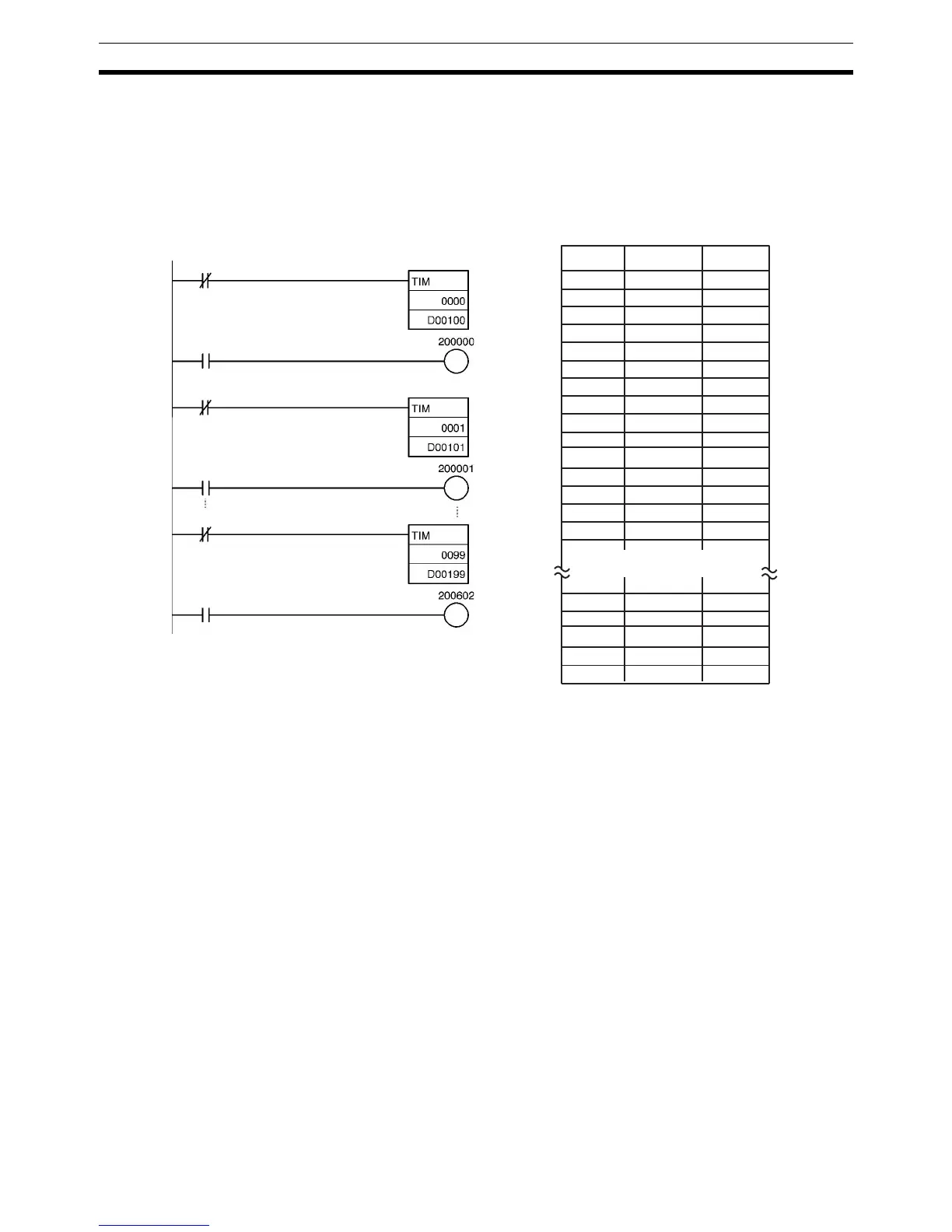
The subroutine above is equivalent to the 400 instructions below.
000000 LD NOT 200000
000001 TIM 0000
D00100
000002 LD T0000
000003 OUT 200000
000004 LD NOT 200001
000005 TIM 0001
D00101
000006 LD T0001
000007 OUT 200001
000008 LD NOT 200002
000009 TIM 0002
D00102
000010 LD T0002
000011 OUT 200002
000396 LD NOT 200602
000397 TIM 0099
D00199
000398 LD T0000
000399 OUT 200602
200000
T0000
200001
T0001
200602
T0099
Instruction OperandsAddress