11
General Instruction Characteristics Section 1-1
The following ladder programming examples show how the index registers are
treated.
Example 1
Ladder Program:
LD P_Off
OUT, IR0+
Operation: When the PLC memory address 000013 is stored in IR0.
The input condition is OFF (P_Off is the Always OFF Flag), so the OUT
instruction sets 000013, which is indirectly addressed by IR0, to OFF. The
OUT instruction is executed, so IR0 is incremented. As a result, the PLC
memory address 000014, which was incremented by +1 in the IR0, is stored.
Therefore, in the following cycle the OUT instruction turns OFF 000014.
Example 2
Ladder Program:
LD P_Off
SET, IR0+
Operation: When the PLC memory address 000013 is stored in IR0.
The input condition is OFF (P_Off is the Always OFF Flag), so the SET
instruction is not executed. Therefore, IR0 is not incremented and the value
stored in IR0 remains PLC memory address 000013.
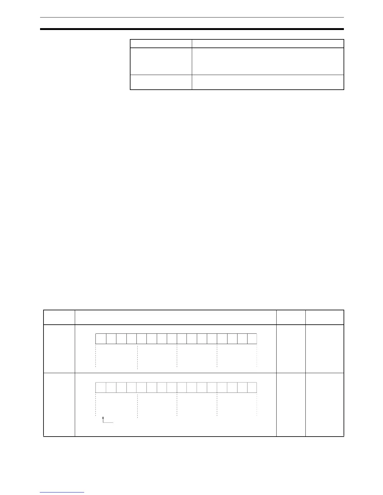
1-1-6 Data Formats
The following table shows the data formats that can be used in CS/CJ-series
PLCs.
Block programming
instructions
BPPS(811), BPRS(812), EXIT(806), EXIT(806) NOT,
IF(802), IF(802) NOT, WAIT(805), WAIT(805) NOT,
TIMW(813)/TIMWX(816), CNTW(814)/CNTWX(818),
TMHW(815)/TMHWX(817), LEND(810), LEND(810) NOT
Text string processing
instructions
STRING COMPARISON (LD, AND, OR = $, etc. (function
codes: 670 to 675))
Classification Instructions
Name Format Decimal
range
Hexadecimal
range
Unsigned
binary
data
0 to
65,535
0000 to FFFF
Signed
binary
data
–32,768
to
+32,767
8000 to 7FFF
15 14 13 12 11 10 9 8 7 6 5 4 3 2 1 0
2
15
2
14
2
13
2
12
2
11
2
10
2
9
2
8
2
7
2
6
2
5
2
4
2
3
2
2
2
1
2
0
2
3
2
2
2
1
2
0
2
3
2
2
2
1
2
0
2
3
2
2
2
1
2
0
2
3
2
2
2
1
2
0
32768
512 256 128 64 32 16 8 4 2 116384 8192 4096 2048 1024
Decimal
Binary
Hexa-
decimal
15 14 13 12 11 10 9 8 7 6 5 4 3 2 1 0
2
15
2
14
2
13
2
12
2
11
2
10
2
9
2
8
2
7
2
6
2
5
2
4
2
3
2
2
2
1
2
0
2
3
2
2
2
1
2
0
2
3
2
2
2
1
2
0
2
3
2
2
2
1
2
0
2
3
2
2
2
1
2
0
-32768
512 256 128 64 32 16 8 4 2 116384 8192 4096 2048 1024
Decimal
1: Ne